
Tool pan back-loading type device for changing tool of slurry-balanced shield machine under normal pressure

A mud-water balance and shield machine technology, which is applied in mining equipment, earth-moving drilling, tunnels, etc., can solve the problems of high risk, high cost, and unfavorable health of operators.

Inactive Publication Date: 2012-01-18
SHENYANG HEAVY MACHINERY GROUP
View PDF9 Cites 39 Cited by
  • Summary
  • Abstract
  • Description
  • Claims
  • Application Information

AI Technical Summary

Problems solved by technology

Usually, during the construction process, tool replacement needs to enter the excavation chamber with a pressure much higher than the atmospheric pressure through the man gate for tool change under pressure. Entering the warehouse under pressure to replace the tool is extremely risky to the operator and is also very harmful to the health of the operator. In addition, the operator can only work for a short time in the excavation chamber, and it takes a long time to replace the tools. Another way is to dig a shaft for tool replacement, but this method is expensive, takes a long time, and is limited by the formation, such as muddy water When the shield machine is operating under the river, it is impossible to drill shafts

Method used


Image

  • Tool pan back-loading type device for changing tool of slurry-balanced shield machine under normal pressure
  • Tool pan back-loading type device for changing tool of slurry-balanced shield machine under normal pressure
  • Tool pan back-loading type device for changing tool of slurry-balanced shield machine under normal pressure

Examples


Embodiment Construction

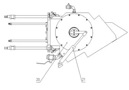
[0013]Referring to the accompanying drawings, a back-mounted normal-pressure tool changing device for a mud-water balance shield machine cutter head consists of a cutter head 1, a first sealing ring 2, a cutter seat 3, a cutter head fixing sleeve 4, a cutter head fixing bolt 5, and a cutter bar 6. Cylindrical gate 7, grease injection valve 8, second sealing ring 9, screw rod 10, first fixing screw 11, small end cover 12, screw nut 13, guide rod 14, nut 15, flushing valve 16, third seal Ring 17, fourth sealing ring 18, bearing 19, large end cover 20, oil cylinder 21, fifth sealing ring 22, second fixing screw 23, sixth sealing ring 24, when the cutter is in working state, the cutter head 1 passes through the cutter head The fixed sleeve 4 and the cutter head fixing bolt 5 are fixed on the cutter bar 6, the front end of the cutter bar is equipped with a sealing ring 2, the cutter bar 6 cooperates with the front end of the cutter seat 3, and is sealed by the sealing ring 2, and th...


PUM


Abstract

The invention relates to a tool pan back-loading type device for changing a tool of a slurry-balanced shield machine under normal pressure, which is applied to the technical field of shield machine engineering machinery. The tool pan back-loading type device for changing the tool of the slurry-balanced shield machine under normal pressure comprises a tool bit, a first seal ring, a tool post, a tool bit fixing sleeve, a tool bit fixing bolt, a tool bar, a cylindrical gate, a grease injection valve, a flushing valve, a third seal ring, a fourth seal ring, a bearing, a large end cover, an oil cylinder and the like; when the tool is in the working state, the tool bit is fixed on the tool bar through the tool bit fixing sleeve and the tool bit fixing bolt; the first seal ring is mounted at thefront end of the tool bar, and the tool bar is matched with the front end of the tool post and is sealed through the first seal ring; the tool bar is fixed on the tool post by the rear end of the tool bar and the tool post through a first fixing screw; the cylindrical gate is fixed on the tool post through the bearing and the large end cover; the grease injection valve and the flushing valve are installed on the tool post; and a serial number is arranged between the cylindrical gate and the tool post. The tool pan back-loading type device for changing the tool of the slurry-balanced shield machine under normal pressure has the advantages of simple structure, reliable working, and capability of conveniently and quickly changing a worn tool under normal pressure (atmospheric pressure) in the shield construction process.

Description

technical field [0001] The invention belongs to the technical field of shield tunneling machine engineering machinery, and is mainly aimed at the structure of a back-mounted atmospheric pressure tool changing device for a mud-water balance shield machine cutter head and the application of tool replacement. Background technique [0002] At present, the mud-water balance shield machine mainly relies on the knives installed on the cutter head to excavate the clay, sand and rocks on the excavation surface. During the shield construction process, the knives are easy to wear and need to be replaced frequently. Usually, during the construction process, tool replacement needs to enter the excavation chamber with a pressure much higher than the atmospheric pressure through the man gate for tool change under pressure. Entering the warehouse under pressure to replace the tool is extremely risky to the operator and is also very harmful to the health of the operator. In addition, the ope...

Claims


Application Information

Patent Timeline
IPC IPC(8): E21D9/08
Inventor 秦立学高伟贤苏鹏程何恩光邓立营党军锋肖羽曼赵海峰
Owner SHENYANG HEAVY MACHINERY GROUP
Learn More