Beam current transmission system and method

A technology of current transmission and beam current, which is applied in the direction of discharge tubes, electrical components, circuits, etc., can solve the problems of low beam current intensity and long beam transmission path, so as to improve the beam current intensity, improve the uniformity of injection dose and inject Angle uniformity, the effect of improving process efficiency

Active Publication Date: 2012-01-11
KINGSTONE SEMICONDUCTOR LIMITED COMPANY
View PDF4 Cites 5 Cited by
  • Summary
  • Abstract
  • Description
  • Claims
  • Application Information

AI Technical Summary

Problems solved by technology

[0006] The technical problem to be solved by the present invention is to overcome the defect that the number of beam optical elements in the beam transmission system of the prior art is relatively large, so that the beam transmission path is long and the beam intensity reaching the target workpiece is low, providing A beam transmission system capable of shortening the beam transmission path, thereby increasing the beam intensity reaching a target workpiece, and a corresponding beam transmission method

Method used


Image

  • Beam current transmission system and method
  • Beam current transmission system and method
  • Beam current transmission system and method

Examples


Embodiment Construction

[0018] The preferred embodiments of the present invention are given below in conjunction with the accompanying drawings to describe the technical solution of the present invention in detail.

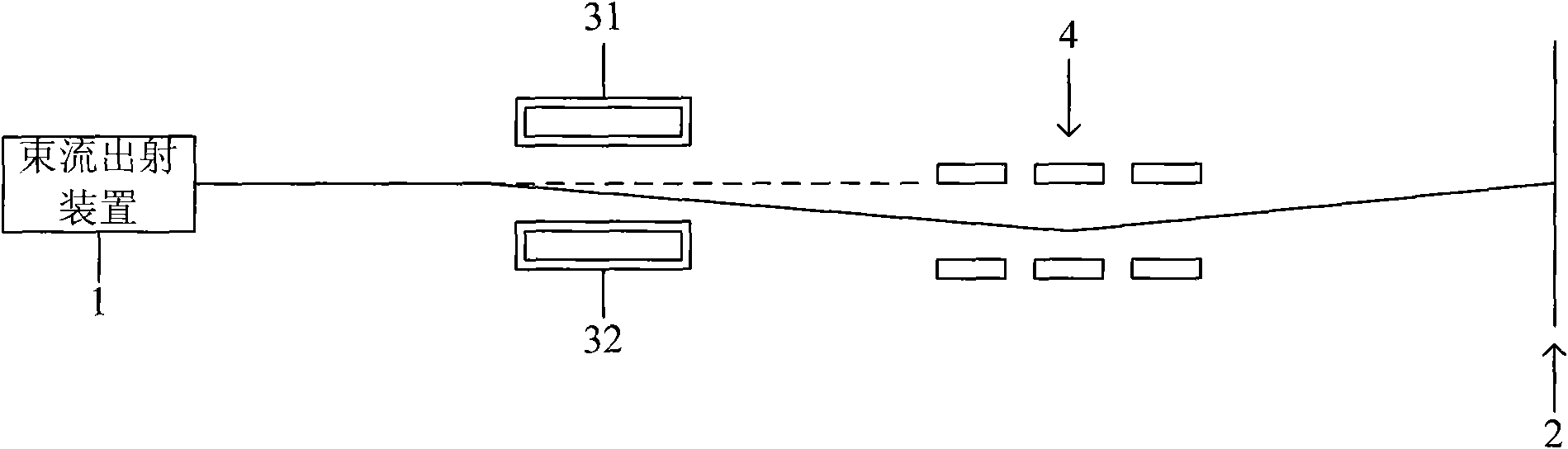
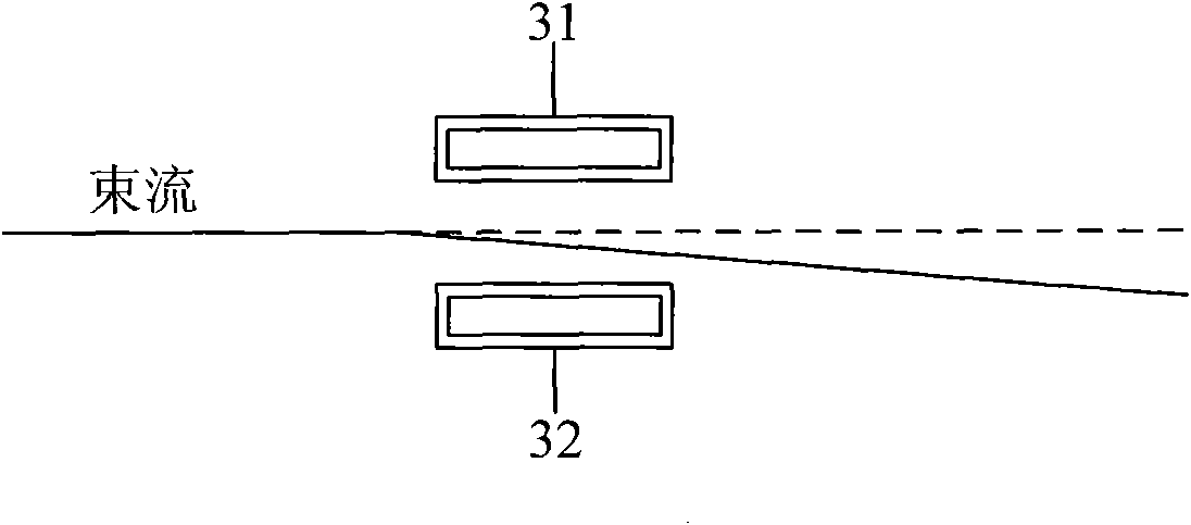
[0019] refer to figure 1 As shown, the beam transmission system of the present invention firstly includes a beam output device 1 as the starting point of the beam transmission and a target workpiece 2 as the end point of the beam transmission. The beam exit device 1 is used to generate an ion beam or an electron beam. During the transmission of the beam, its transmission state will be controlled by various beam optical elements arranged on the beam transmission path, so that when the beam When the flow finally reaches the target workpiece 2, various state parameters such as its intensity distribution and angular distribution can meet the preset requirements of the process, so as to achieve better injection dose uniformity and Injection angle uniformity.

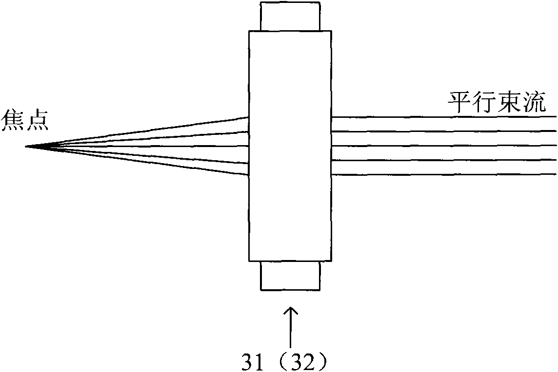
[0020] In particular, in the b...


PUM


Abstract

The invention discloses a beam current transmission system, which comprises a beam current emerging device and a target workpiece serving as a beam current transmission terminal point, wherein a pair of relatively parallel rod-shaped quadrupole magnets which is positioned on two sides of a beam current transmission path is arranged between the beam current emerging device and the target workpiece. The invention also discloses a beam current transmission method which is implemented by using the beam current transmission system. By using the pair of rod-shaped quadrupole magnets, the transmission path of beam current is shortened and the transmission efficiency of the beam current and the strength of the beam current reaching the target workpiece are improved; furthermore, the strength distribution and the angle distribution of the beam current can be controlled conveniently, so that the utilization efficiency of the beam current is improved; moreover, the uniformity of injection dosages and injection angles of the beam current can be improved.

Description

technical field [0001] The invention relates to the field of semiconductor manufacturing, in particular to a beam transmission system and method. Background technique [0002] Transport control of ion or electron beams is required in many areas of manufacturing. For example, the ion implantation method is used to introduce atoms or molecules, which are usually called impurities, into the target substrate, thereby changing the properties of the substrate material. For example, metal bearings are introduced into other materials through ion implantation, which can improve their wear resistance and prolong their service life. The ion coating method is to deposit ionic materials on the surface of the workpiece, thereby changing the physical and chemical properties of the surface of the workpiece, such as the manufacture of optical devices or display equipment, it is necessary to adopt a thin film deposition process with controllable thickness and predetermined surface properties ...

Claims


Application Information

Patent Timeline
Patent Type & Authority Applications(China)
IPC IPC(8): H01J37/147H01J37/32
Inventor 钱锋陈炯
Owner KINGSTONE SEMICONDUCTOR LIMITED COMPANY
Why Eureka
Try Eureka