Apparatus for transporting fuel oil

A conveying device, fuel oil technology, applied in the direction of liquid distribution, conveying or transfer device, distribution device, transportation and packaging, etc.

Active Publication Date: 2012-01-11
HOKUSHIN ENG
View PDF5 Cites 7 Cited by
  • Summary
  • Abstract
  • Description
  • Claims
  • Application Information

AI Technical Summary

Problems solved by technology

[0007] However, in the absence of the above-mentioned valve 15 figure 1 In the device, when part of the heated fuel in the fuel oil settling tank and / or the fuel daily tank flows down to the fuel storage tank, the fuel will not return to the fuel storage tank but flow back to the direction of the delivery pipeline

Method used


Image

  • Apparatus for transporting fuel oil
  • Apparatus for transporting fuel oil
  • Apparatus for transporting fuel oil

Examples


Embodiment Construction

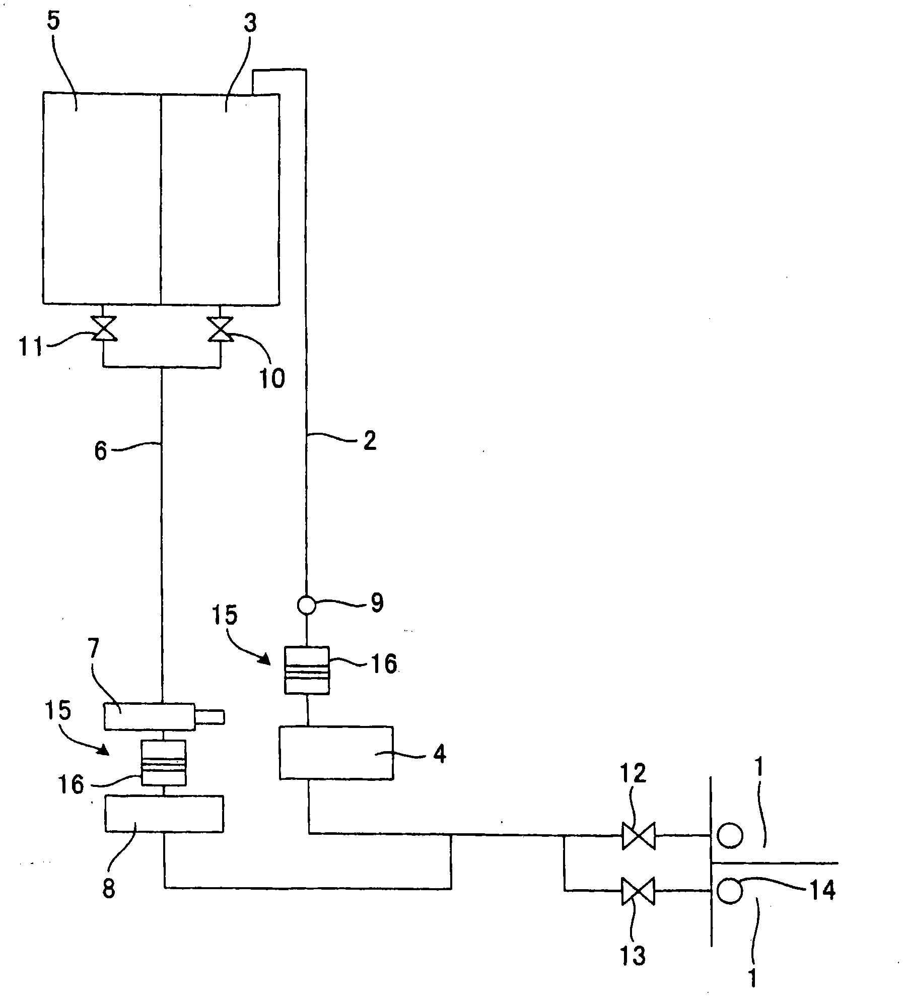
[0017] exist figure 1 Among them, the fuel delivery device of the present invention has: a fuel storage cabinet 1, which has a main suction pipe 14; a fuel oil settling cabinet 3, which communicates with the fuel storage cabinet 1 via a delivery pipeline 2; a delivery pump 4, which is arranged in the delivery pipeline 2, and uses The fuel oil in the fuel storage cabinet 1 is transported to the fuel sedimentation tank 3 through the delivery pipeline 2; the daily fuel tank 5 communicates with the fuel sedimentation tank 3; the suction pipeline 6 connects the fuel storage tank 1 with the fuel sedimentation tank 3 and / or Or the daily fuel tank 5 is connected; the flow down pump 7 is arranged in the suction pipe 6 to make the heated fuel in the fuel settling tank 3 and / or the fuel daily tank 5 flow down to the fuel storage tank 1 . The heated fuel flows down through the suction main pipe 14 and mixes with the fuel in the fuel storage tank 1 to heat the fuel in the fuel storage tank...


PUM


Abstract

The invention provides an apparatus for transporting fuel oil. Heated fuel oil flows through a suction main pipeline (14) and then is mixed with the fuel oil inside a fuel storage cabinet (1). Then the fuel oil inside the fuel storage cabinet (1) is heated. A valve (15) for retaining a spring is equipped on the downstream of a conveying pump (4) of a conveying pipeline (2). Another valve (15) for retaining a spring is also equipped on the downstream of a downflow pump (7) of a suction pipeline (6). The heated fuel oil inside a fuel oil deposition cabinet (3) and / or a fuel oil daily cabinet (5) is made not to flow back to a conveying pipeline (12). The heated fuel oil inside a fuel oil deposition cabinet (3) and / or a fuel oil daily cabinet (5) is further prevented from flowing down towards the suction pipeline (6). Naturally flowing down is prevented. And the fuel oil is then conveyed to a storage cabinet.

Description

technical field [0001] The present invention relates to a fuel delivery device for boilers of ships, generators, etc. : サ一ビススタンク) The fuel delivery device in which the heated fuel naturally flows down or counterflows during the stop process. Background technique [0002] In ships, etc., when fuel is supplied to the engine of the mechanism, the fuel oil is usually sent from the fuel storage tank to the fuel oil settling tank through the delivery pipeline by using the delivery pump, and then sent from the fuel oil settling tank to the daily fuel tank (commonly used fuel oil) tank), from which the daily fuel tank is used to supply fuel to the engine of the mechanism. At this time, heating is required in order to lower the viscosity of the fuel in the fuel storage tank to facilitate fuel transfer. [0003] As this kind of fuel delivery device with heating equipment, it is known in the past that it does not have the following figure 1 The device of the valve 15 has: a fuel sto...

Claims


Application Information

Patent Timeline
IPC IPC(8): F02M37/18F23K5/04
CPCB63H21/38B67D7/36B67D7/58B67D7/78
Inventor 千千波孝泰
Owner HOKUSHIN ENG
Why Eureka
Try Eureka