Heat treatment furnace for steel cylinders

A technology for heat treatment furnaces and steel cylinders, applied in heat treatment furnaces, heat treatment equipment, furnaces, etc., can solve problems such as uneven transportation and scratches on the outer surface of steel cylinders, and achieve the effects of low cost, simple processing, and simple structure

Inactive Publication Date: 2012-01-11
张家港市嘉华炉业有限公司
View PDF8 Cites 3 Cited by
  • Summary
  • Abstract
  • Description
  • Claims
  • Application Information

AI Technical Summary

Problems solved by technology

Its disadvantages are: since most of the steel cylinders have a cylindrical structure, and the conveying roller is also a cylindrical structure, when the steel cylinder is placed on the conveying roller, the steel cylinder is very easy to roll on the conveying roller, resulting in unstable conveying and easy to make the cylinder outside The surface is scratched due to the collision with the furnace body

Method used


Image

  • Heat treatment furnace for steel cylinders
  • Heat treatment furnace for steel cylinders
  • Heat treatment furnace for steel cylinders

Examples


Embodiment Construction

[0011] The steel cylinder heat treatment furnace of the present invention will be described in further detail below through specific examples.

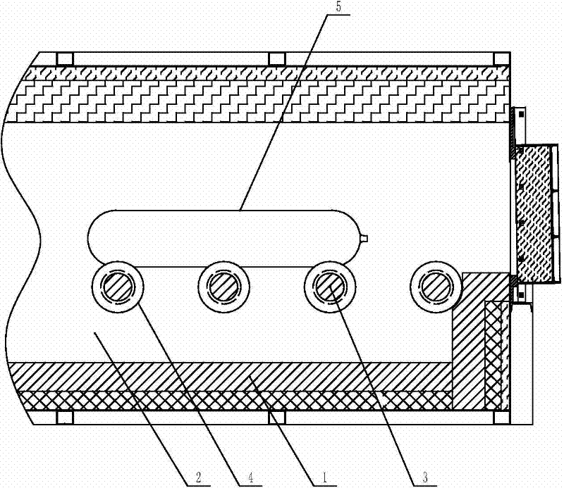
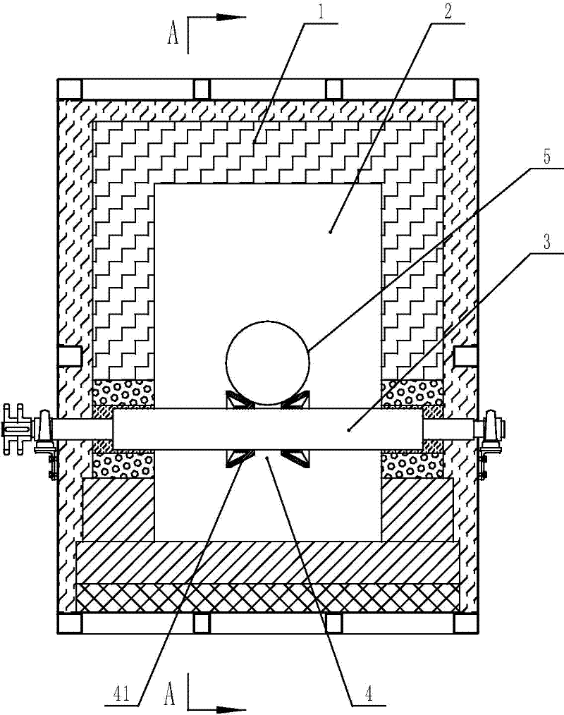
[0012] Such as figure 1 , figure 2 As shown, the steel cylinder heat treatment furnace includes a furnace body 1. A heat treatment chamber 2 is arranged in the furnace body 1. A conveying roller table is arranged in the heat treatment chamber 2. The conveying roller table is formed by arranging several conveying rollers 3. Two conveying rollers 3 The end movement is arranged in the furnace body 1, and the middle part of each conveying roller 3 is respectively covered with a limit sleeve 4, which is arranged in a straight line along the conveying direction of the conveying roller table, and the outer wall of the limit sleeve 4 is provided with an annular concave groove. In this embodiment, the structure of the limiting sleeve 4 includes two conical wheels 41 , and the conical surfaces of the two conical wheels 41 are arranged opposi...


PUM


Abstract

The invention relates to a heat treatment furnace for steel cylinders. The heat treatment furnace comprises a furnace body; a heat treatment cavity is arranged in the furnace body and is provided with a roller conveyer which is formed from arrangement of a plurality of transport rollers; two ends of a transport roller are movably arranged in the furnace body; each transport roller is sleeved with a stop collar; the stop collars are linearly arranged along the conveying direction of the roller conveyer; the outer wall of each stop collar is provided with an annular groove. The heat treatment furnace provided in the invention is applicable for heat treatment on steel cylinders in the production process of steel cylinders and enables the steel cylinders to uniformly absorb heat and to be transported smoothly during heat treatment; with utilization of the heat treatment furnace, the surface of the steel cylinders is not easy to be scratched.

Description

technical field [0001] The invention relates to the technical field of steel cylinder production equipment, in particular to a steel cylinder heat treatment furnace. Background technique [0002] The structure of the currently used steel cylinder heat treatment furnace includes a furnace body. A heat treatment chamber is arranged in the furnace body. A conveying roller table is arranged in the heat treatment chamber. The conveying roller table is formed by arranging several conveying rollers. in the furnace body. When the steel cylinder heat treatment furnace mentioned above is heat-treating the steel cylinder, the steel cylinder is placed on the conveying roller, and the conveying roller is driven by the driving device to rotate, so that the steel cylinder is continuously conveyed forward. Its disadvantages are: since most of the steel cylinders have a cylindrical structure, and the conveying roller is also a cylindrical structure, when the steel cylinder is placed on the ...

Claims


Application Information

Patent Timeline
Patent Type & Authority Applications(China)
IPC IPC(8): C21D9/00F27B9/24
Inventor 陈健
Owner 张家港市嘉华炉业有限公司
Why Eureka
Try Eureka