Quasi-resonant control circuit of inverter

A quasi-resonance control and time control circuit technology, which is applied in the direction of electrical components, high-efficiency power electronic conversion, output power conversion devices, etc., can solve the problem of high requirements for frequency reduction quasi-resonance control methods, and achieve the effect of quasi-resonance control optimization

Active Publication Date: 2013-09-11
ALTENERGY POWER SYST
View PDF4 Cites 0 Cited by
  • Summary
  • Abstract
  • Description
  • Claims
  • Application Information

AI Technical Summary

Problems solved by technology

Such frequency reduction quasi-resonance control method has high requirements on hardware and software

Method used


Image

  • Quasi-resonant control circuit of inverter
  • Quasi-resonant control circuit of inverter
  • Quasi-resonant control circuit of inverter

Examples


Embodiment Construction

[0061] The present invention will be further described below in conjunction with specific embodiment and accompanying drawing, set forth more details in the following description so as to fully understand the present invention, but the present invention can obviously be implemented in a variety of other ways different from this description, Those skilled in the art can make similar promotions and deductions based on actual application situations without violating the connotation of the present invention, so the content of this specific embodiment should not limit the protection scope of the present invention.

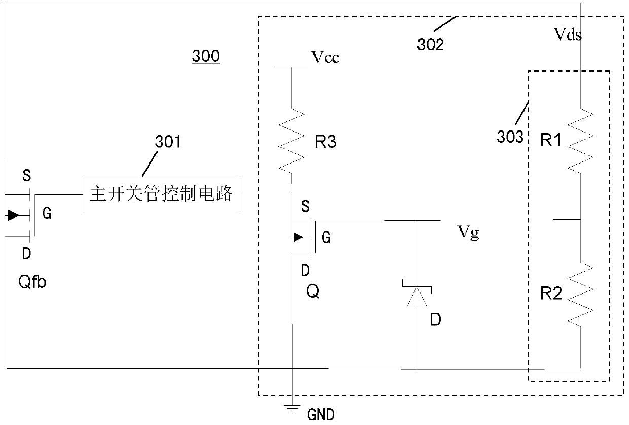
[0062] Figure 4 It is a schematic diagram of a quasi-resonant control circuit of an inverter according to an embodiment of the present invention. Such as Figure 4 As shown, the quasi-resonance control circuit 400 may include a main switch control circuit 401 , a quasi-resonance time control circuit 402 and a quasi-resonance detection circuit 403 . Wherein, one end o...


PUM


Abstract

The invention provides a quasi-resonant control circuit of an inverter, comprising a quasi-resonant detection circuit, a quasi-resonant time control circuit and a main switching tube control circuit, wherein one end of the quasi-resonant detection circuit is connected with a source terminal of a main switching tube of the inverter and the other end of the quasi-resonant detection circuit is connected with a public earth terminal, and the quasi-resonant detection circuit is used for detecting a quasi-resonant function of starting the main switching tube in accordance with the drain-source voltage of the main switching tube and then sending out quasi-resonant control signals; the quasi-resonant time control circuit is connected with the quasi-resonant detection circuit and used for receiving the quasi-resonant control signals and carrying out time delay; and the main switching tube control circuit is bridged between the quasi-resonant time control circuit and a grid terminal of the main switching tube and used for switching on or off the main switching tube in accordance with the signals output by the quasi-resonant time control circuit. The quasi-resonant control circuit can optimize the quasi-resonant control of the inverter in the wider input voltage range and realize the low input power and the quasi-resonant control of the low phase of AC (alternating current) output as well.

Description

technical field [0001] The invention relates to the technical field of quasi-resonance detection and control, in particular, the invention relates to a quasi-resonance control circuit of an inverter. Background technique [0002] In the existing inverter field, quasi-resonant technology is a widely used method to increase efficiency, improve reliability and reduce cost. It makes the main switching tube of the inverter open at the trough of the voltage at both ends, thereby reducing the energy loss of the main switching tube, and sometimes the voltage at both ends may drop to zero. By controlling the turn-on and turn-off time of the main switching tube, the quasi-resonant switching function can be realized, thereby effectively reducing energy loss and improving efficiency. Quasi-resonant technology reduces MOSFET switching losses, thereby increasing reliability. In addition, softer switching can improve the EMI characteristics of the power supply, allowing designers to redu...

Claims


Application Information

Patent Timeline
Patent Type & Authority Patents(China)
IPC IPC(8): H02M7/5383
CPCY02B70/1441Y02B70/10
Inventor 罗宇浩张圣
Owner ALTENERGY POWER SYST
Why Eureka
Try Eureka