Roller bottom type continuous heating furnace for track shoe

A roller hearth type, heating furnace technology, applied in heat treatment furnaces, furnaces, furnace types, etc., can solve problems such as furnace door falling, difficulty in ensuring workpiece alignment and rolling out, and difficulty in determining furnace door opening and closing times. The effect of reducing, shortening time, and reducing overflow loss

Inactive Publication Date: 2014-01-08
SHANDONG JIANZHU UNIV
View PDF10 Cites 0 Cited by
  • Summary
  • Abstract
  • Description
  • Claims
  • Application Information

AI Technical Summary

Problems solved by technology

[0007] During the running and heating process of the workpiece, due to the deformation of the workpiece itself and the different friction coefficients, even if two rows of workpieces of the same specification are aligned front and rear during the furnace loading process, when the workpieces run to the exit, the left and right workpieces in each row The relative position of the workpiece will also change back and forth, which makes it difficult to determine the opening and closing time of the furnace door when the workpiece comes out of the furnace, or the furnace door has fallen when the workpieces have not all rolled out of the furnace body, or there are two workpieces rolled out at a time in a row, which is difficult Ensure that the workpieces in the same row are aligned and rolled out at one time, so that the subsequent press quenching equipment cannot work, and it is difficult to control the temperature drop above the track shoe line

Method used


Image

  • Roller bottom type continuous heating furnace for track shoe
  • Roller bottom type continuous heating furnace for track shoe
  • Roller bottom type continuous heating furnace for track shoe

Examples


Embodiment Construction

[0026] In order to clearly illustrate the technical characteristics of this solution, the following will describe this solution through specific implementation modes and in conjunction with the accompanying drawings.

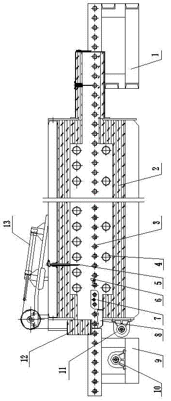
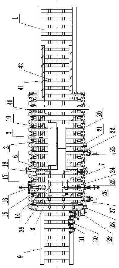
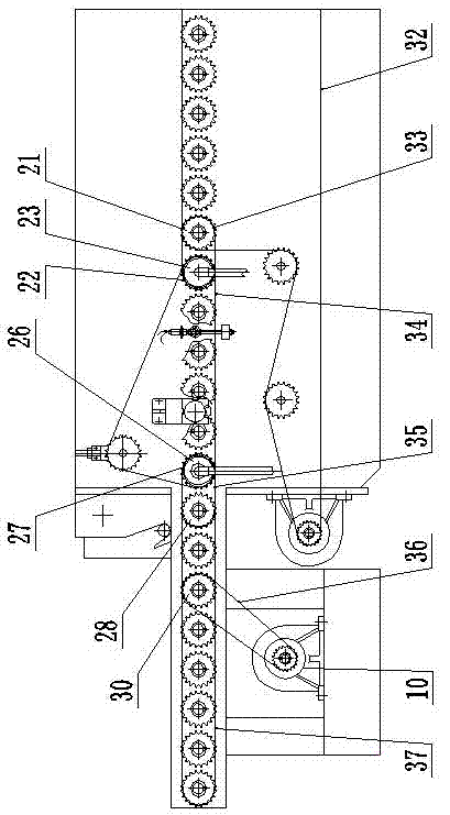
[0027] A crawler roller hearth type continuous heating furnace, as shown in the figure, it includes a furnace body 2 with a furnace door 12 and a casing, and a feeder 1 and a discharger 9 positioned at two ends of the furnace body 2, the feeder Each transmission roller 3 of the transmission mechanism in the feeder 1 , the discharger 9 and the furnace body 2 is provided with at least two guide grooves 40 for making the workpieces 19 run in a row. The guide groove 40 includes an inner limit ring 42 and an outer limit ring 41 . Wherein, on the two adjacent drive rollers 3 located at the outlet end of the heating part in the furnace body 2, the outer limit ring 41 adopts a limit device for closing or opening the guide groove 40; The detection device for the signal, t...


PUM


Abstract

The invention provides a roller bottom type continuous heating furnace for a track shoe. The roller bottom type continuous heating furnace for the track shoe comprises a furnace body with a furnace door and a shell, and a feeding machine and a charging machine which are positioned at the two ends of the furnace body, wherein each driving roller of the feeding machine, the discharging machine and a transmission mechanism of the furnace body is provided with at least two guide grooves which enable workpieces to run in a row. The roller bottom type continuous heating furnace for the track shoe is characterized in that each guide groove comprises an inner limiting ring and an outer limiting ring; the outer limiting rings adopt limiting devices, which are used for closing or opening the guide grooves, on the two adjacent driving rollers positioned at the outlet end of a heating part of the furnace body in the furnace body; the roller bottom type continuous heating furnace for the track shoe also comprises detection devices for detecting front end position signals of the workpieces; and the detection devices and the limiting device are arranged sequentially along the running direction of the workpieces, and cooperate to guarantee that the workpieces are output after the front ends of the workpieces are aligned. The heating furnace can guarantee that the left and right workpieces in the same row are discharged from the furnace after being aligned with each other, and provides reliable workpiece position guarantee to the subsequent heat treatment link.

Description

technical field [0001] The invention relates to a heating furnace, in particular to a crawler roller hearth type continuous heating furnace. Background technique [0002] Commonly used track shoes are divided into 135-228 according to the pitch, the plate width is 154-266, the thickness between the teeth is 7-17, and the plate length of each specification is 400-800; according to the tooth shape, it is divided into: single-tooth track Plates and three-tooth track shoes. It can be seen that there are various specifications and varieties of track shoes. Therefore, heat treatment equipment is required to have a high adaptability to meet the needs of modern enterprises for mass production. [0003] Track shoe materials are mostly selected: 23MnB, 25MnB, 25CrMnB materials, which have low carbon content (the measured carbon content of 23MnB is 0.17%), and require a high critical cooling rate during quenching, and multi-phase may appear if the quenching process is a little careles...

Claims


Application Information

Patent Timeline
Patent Type & Authority Applications(China)
IPC IPC(8): C21D9/00
Inventor 王献忠孙德明张保议徐勇王志刚李永胜吴俊平
Owner SHANDONG JIANZHU UNIV
Why Eureka
Try Eureka