
Bonding and potting method for aerial integrated motor

An integral, potting material technology, used in the field of gluing and potting, can solve the problems of large commutation sparks, easily affecting product performance, and the commutator cannot be separated from the surface of the shell, and achieves the effect of overcoming roundness deviation.

Inactive Publication Date: 2012-01-04
FLIGHT AUTOMATIC CONTROL RES INST
View PDF6 Cites 9 Cited by
  • Summary
  • Abstract
  • Description
  • Claims
  • Application Information

AI Technical Summary

Problems solved by technology

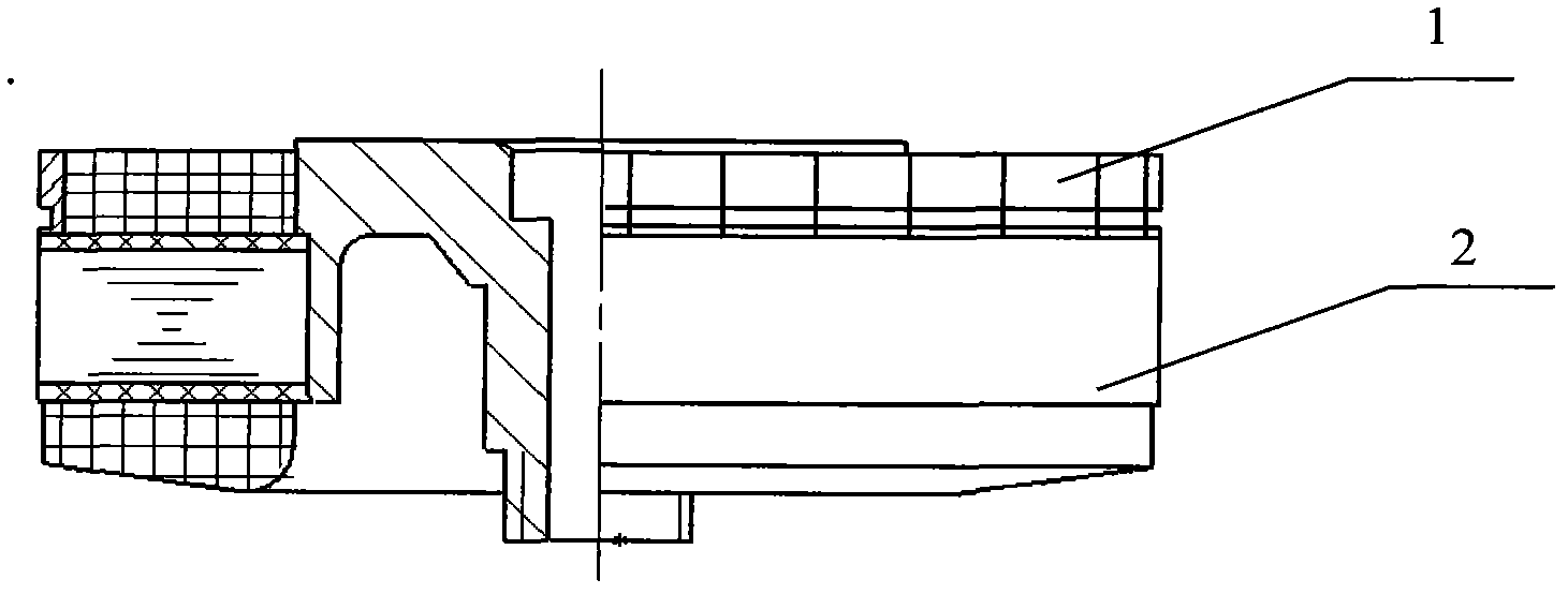
[0002] The structure of the traditional motor commutator is a plug-in type, see the attached figure 1 After the stator and rotor are wound, the commutator 1 is installed to become the winding 2, and the potting mold is used for potting, and finally assembled with reeds and other parts to form a motor. The defect is that the commutator is not round enough to cause commutation sparks Larger, it is easy to affect the product performance, so a new type of integral motor was invented, that is, the structure of the integral motor is shown in the appendix of the manual. figure 2 , the end face commutator is used, the process flow is to wind the stator and weld it directly with the commutator to form a stator winding, and then bond the component to the shell, the coaxiality depends on the bonding The fixture is guaranteed, and the whole motor is potted with elastic epoxy material, and the end face of the commutator cannot be damaged after potting, and the commutator cannot be separated from the surface of the shell during subsequent machining

Method used


Image

  • Bonding and potting method for aerial integrated motor
  • Bonding and potting method for aerial integrated motor
  • Bonding and potting method for aerial integrated motor

Examples


example 1

[0072] Example 1, ×××× overall motor potting:

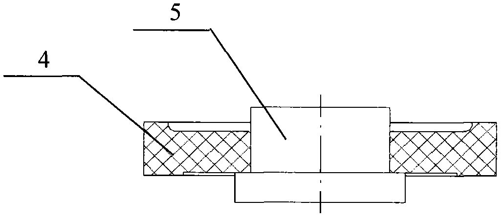
[0073] The elastic film potting mold is composed of an outer mold 4 and a positioning column 5. The outer mold 4 has a central hole, and the positioning column 5 is a cylinder with a step, which is installed on the central hole of the outer mold 4. One end of the outer mold 4 has a Counterbore, the inner diameter of which is the required outer diameter of the elastic film, and the depth is the required thickness of the elastic film;

[0074] The method of potting elastic film is as follows:

[0075] 1. Install the mold; put the positioning column 5 into the outer mold 4, seal the joint surface with silicone rubber, and place it at room temperature for more than 4 hours;

[0076] 2. Preheating; put the potting mold in a 60°C oven to preheat for 0.5h:

[0077] 3. Degassing; put the stirred elastic film potting material into the vacuum chamber to evacuate to remove air bubbles, start timing when the vacuum degree is less than 30Pa...


PUM


Abstract

The invention relates to a bonding and potting technology method for an aerial integrated motor, wherein the method covers a bonding method, preparation of a potting material for an elastic film, a potting die and a potting method. According to the invention, an elastic film is employed as a carrier and a characteristic of shape expansion by squeezing is utilized, so that an end commutator is isolated from an adhesive and a potting material and it can be ensured that there is no superfluity at the surface of the commutator after the bonding and potting processing; meanwhile, an axiality after the potting processing can also be ensured. Besides, the elastic film comprises the following components according to mass percentage: 100% of GN 521 raw material; 100% of a GN 521 vulcanizing agent; and 10% to 50% of a filler. According to the invention, bonding and potting production and processing problems of an aerial integrated motor are solved and a purpose that a circularity of a commutator meets a requirement after the bonding and potting processing of the aerial integrated motor can be achieved; meanwhile, an effect that the surface of the commutator on the winding is free of gel after the bonding and potting processing is realized; and a defect of a circularity deviation of an inserted motor can be overcome.

Description

technical field [0001] The invention relates to a bonding and potting method, in particular to a bonding and potting method for an aviation integral motor. Background technique [0002] The structure of the traditional motor commutator is a plug-in type, see the attached figure 1 After the stator and rotor are wound, the commutator 1 is installed to become the winding 2, and the potting mold is used for potting, and finally assembled with reeds and other parts to form a motor. The defect is that the commutator is not round enough to cause commutation sparks Larger, it is easy to affect the product performance, so a new type of integral motor was invented, that is, the structure of the integral motor is shown in the appendix of the manual. figure 2 , the end face commutator is used, the process flow is to wind the stator and weld it directly with the commutator to form a stator winding, and then bond the component to the shell, the coaxiality depends on the bonding The fix...

Claims


Application Information

Patent Timeline
IPC IPC(8): H02K15/12
Inventor 王葵罗吉勤刘炳刚酒晨霄
Owner FLIGHT AUTOMATIC CONTROL RES INST
Learn More