Gap seal hydraulic cylinder based on deformable piston ring

A technology for sealing hydraulic pressure and piston rings, applied in the field of hydraulic cylinders, can solve the problems of low volume efficiency of hydraulic cylinders, high cost of replacing pistons, affecting the life of seals, etc., to achieve the effects of improving efficiency, reducing maintenance costs and preventing leakage

Inactive Publication Date: 2012-01-04
WUHAN UNIV OF SCI & TECH
View PDF7 Cites 4 Cited by
  • Summary
  • Abstract
  • Description
  • Claims
  • Application Information

AI Technical Summary

Problems solved by technology

However, the seal of this hydraulic cylinder is still in direct contact with solid objects, which not only affects the further increase of frequency, but also affects the life of the seal
[0003] In recent years, the servo hydraulic cylinders developed by some domestic units have removed the polytetraethylene seals and adopted gap seals, but there are following deficiencies in the application, the volumetric efficiency of the hydraulic cylinder is low, and the volumetric efficiency is lower as the oil supply pressure increases , short life, high cost of replacing the piston, etc.

Method used


Image

  • Gap seal hydraulic cylinder based on deformable piston ring
  • Gap seal hydraulic cylinder based on deformable piston ring
  • Gap seal hydraulic cylinder based on deformable piston ring

Examples


Embodiment 1

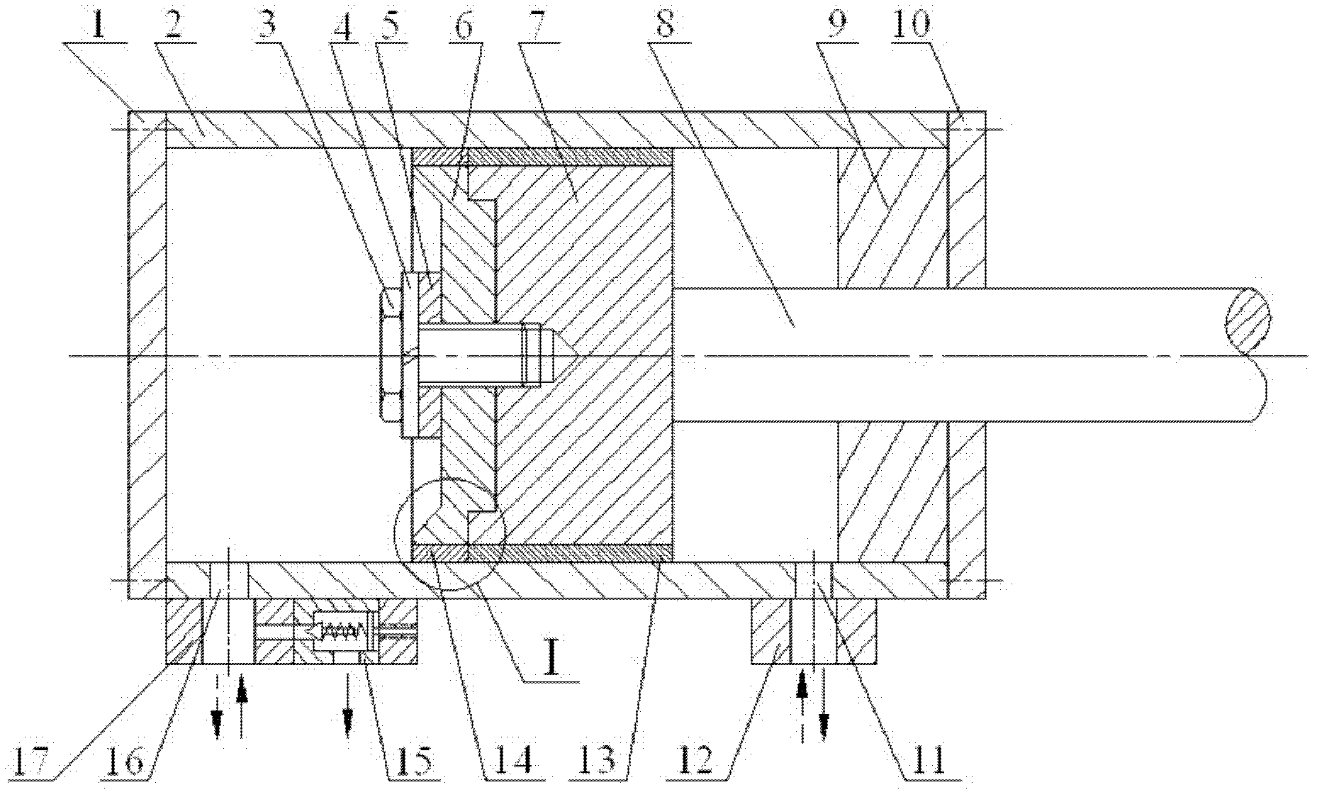
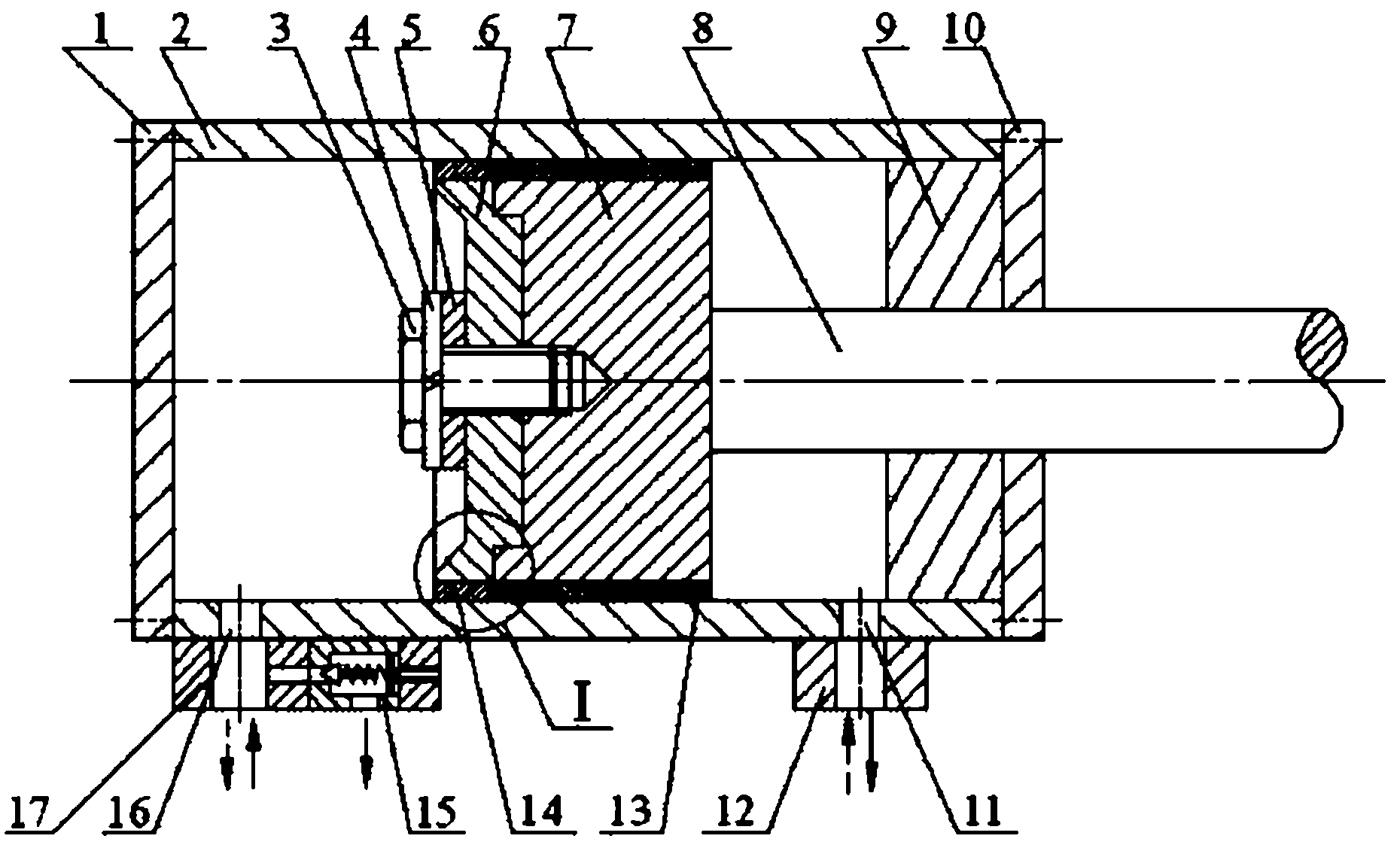
[0019] A gap-sealed hydraulic cylinder based on deformed piston rings. The hydraulic cylinder is figure 1 As shown, the right end surface of the deformed piston ring 6 is composed of a concentric cylindrical boss and an annular bottom surface, the left end surface of the piston 7 is composed of a concentric concave round bottom and an annular boss, and the ring on the left end surface of the piston 7 Shaped boss cross-section is rectangular, and the cylindrical boss outer diameter and height of the right end surface of deformed piston ring 6 are identical with the concave round bottom inner diameter and depth of the left end surface of piston 7 respectively; The cylindrical boss end surface of deformed piston ring 6 Concentrically close to the concave round bottom of the piston 7 and the end surface of the annular boss with the annular bottom surface. The external diameter of deformed piston ring 6 is identical with the external diameter of piston 7, and the center of deforme...

Embodiment 2

[0024] A gap-sealed hydraulic cylinder based on deformed piston rings.

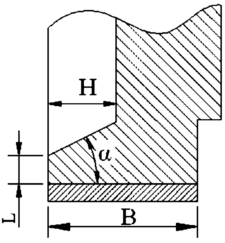
[0025] The height H of the right-angled trapezoid=10~12mm, the length L=1.0~1.2mm of the upper bottom, the included angle α=30~40° between the hypotenuse and the right-angled side of the right-angled trapezoid; the thickness B of the cylindrical surface of the deformed piston ring 6=20~ 25 mm; the layer thicknesses of the first aluminum bronze layer 14 and the second aluminum bronze layer 13 are both 0.8-1.0 mm.

[0026] All the other are with embodiment 1.

Embodiment 3

[0028] A gap-sealed hydraulic cylinder based on deformed piston rings.

[0029] The height H of the right-angled trapezoid=9~11mm, the length of the upper bottom L=0.9~1.1mm, the included angle α=25~35° between the hypotenuse and the right-angled side of the right-angled trapezoid; the thickness B of the cylindrical surface of the deformed piston ring 6=18~ 22 mm; the layer thicknesses of the first aluminum bronze layer 14 and the second aluminum bronze layer 13 are both 0.6-0.8 mm.

[0030] All the other are with embodiment 1.

[0031] Compared with the prior art, this specific embodiment has the following positive effects:

[0032] (1) In this specific embodiment, a concave-convex deformed piston ring 6 is installed on the left end of the piston 7. The cylindrical convex table surface of the deformed piston ring 6 is embedded with the concave round bottom of the piston 7, and the two are concentrically connected by the screw 3. The latter is fastened, and the cylindrical s...


PUM


Abstract

The invention relates to a gap seal hydraulic cylinder based on a deformable piston ring. The hydraulic cylinder provided by the invention is characterized in that the cylindrical boss end face and the annular bottom surface of the deformable piston ring (6) are concentrically and closely clung to the concave round bottom and the annular boss end face of a piston (7); the deformable piston ring (6) and the piston (7) have the same outer diameter; the deformable piston ring (6) is fixed with the piston (7) by a screw (3); the cylindrical surfaces of the deformable piston ring (6) and the piston (7) are correspondingly welded with a first aluminum bronze layer (14) and a second aluminum bronze layer (13); the left end face of the deformable piston ring (6) is composed of a concave round bottom in an obconical frustum shape and an annular boss which are arranged concentrically, and the annular boss with a right-trapezoidal section forms the lip of the deformable piston ring (6); a second valve block (17) is concentrically fixed at an oil port (16) of a rod-less cavity; and a pressure limiting valve (15) is closely clung to a cylinder barrel (2) and is fixed on the second valve block (17). The hydraulic cylinder provided by the invention has the characteristics of long service life, low friction performance, high frequency response, high efficiency, high reliability, low maintenance cost and overload protection performance.

Description

technical field [0001] The invention belongs to the technical field of hydraulic cylinders. In particular, it relates to a gap sealing hydraulic cylinder based on a deformed piston ring. Background technique [0002] Hydraulic cylinders, especially servo hydraulic cylinders, are more and more widely used in the field of hydraulic technology. They are combined with instrumentation, electric control and other technologies in their work, adding new features and new vitality to hydraulic machinery. Due to the environment and conditions of its application, the servo hydraulic cylinder is required to have the characteristics of high response, low friction, no creep, no external leakage, long life, high reliability, etc., so it has special requirements for sealing, support guide and material selection. At present, the successful application of sealing materials is filled polytetraethylene, which has good chemical stability, good wear resistance, heat resistance and oil resistance,...

Claims


Application Information

Patent Timeline
Patent Type & Authority Applications(China)
IPC IPC(8): F16J9/20F16J9/26F16J1/00F16J10/04
Inventor 湛从昌陈奎生付连东陈新元曾良才朱学彪梅元元
Owner WUHAN UNIV OF SCI & TECH
Why Eureka
Try Eureka