
frame camera

A framing and control mechanism technology, which is applied in photography, cameras, high-speed photography, etc., can solve the problems that the framing camera mechanism is not easy to seal and difficult to process, and achieves low leakage rate, easy vacuum sealing, and small internal space occupation Effect

Inactive Publication Date: 2011-12-28
XI'AN INST OF OPTICS & FINE MECHANICS - CHINESE ACAD OF SCI
View PDF5 Cites 2 Cited by
  • Summary
  • Abstract
  • Description
  • Claims
  • Application Information

AI Technical Summary

Problems solved by technology

[0004] The invention provides a framing camera mechanism, which mainly solves the problems that the existing framing camera mechanism is not easy to seal and difficult to process

Method used


Image

  • frame camera
  • frame camera
  • frame camera

Examples


Embodiment Construction

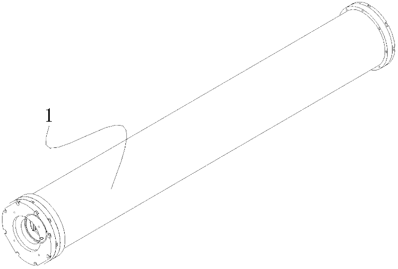
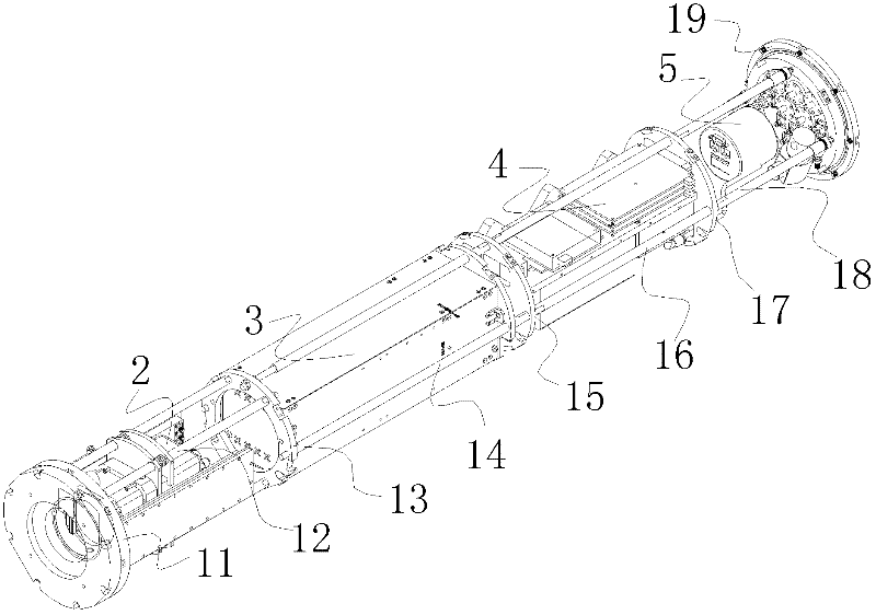
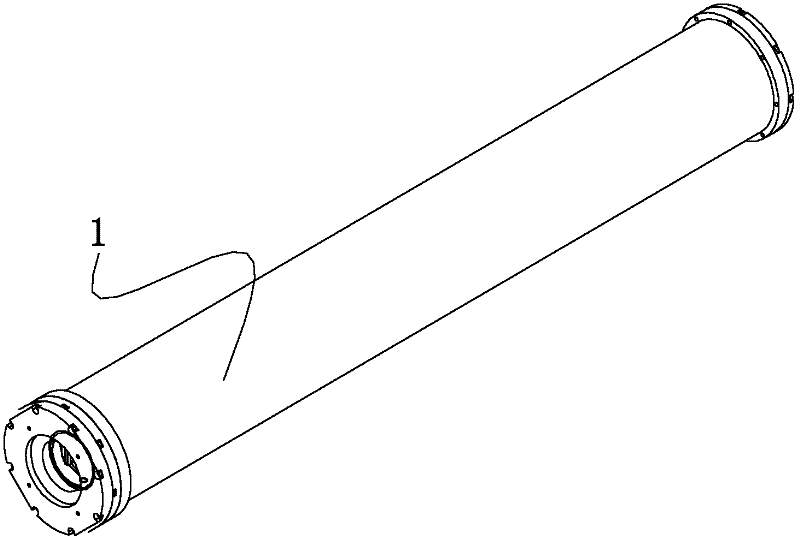
[0016] The present invention is described in detail below in conjunction with accompanying drawing, as figure 1 , figure 2 Shown:

[0017] The framing camera mechanism includes a framing phase tube 2, a CCD3, a power supply and a control mechanism 4, a sensing mechanism 5, and a cylindrical mechanism 1 that are electrically connected in sequence. The cylindrical mechanism 1 includes a bracket and a cylindrical sleeve, and the cylindrical sleeve The inner diameter of the inner diameter matches the outer diameter of the bracket, and the cylindrical sleeve is sleeved on the bracket; the framing phase tube 2, CCD3, power supply and control mechanism 4 and sensing mechanism 5 are arranged in the bracket of the cylindrical mechanism 1.

[0018] The bracket includes a front panel 11, a connecting rod 12, an adapter plate 13, a moving connecting rod 14, a first serial connection rod 16, a first serial connection board 15, a second serial connection rod 18, a second serial connection...


PUM


Abstract

The invention relates to a high-speed technique for photography, and particularly relates to a camera shooting mechanism which is mainly used for solving the problems that the existing camera shooting mechanism is not easy to seal and is difficult to process. The camera shooting mechanism comprises a framing image tube, a charge coupled device (CCD), a power source control mechanism, a sensing mechanism and a cylindrical mechanism, wherein the cylindrical mechanism comprises a bracket and a cylindrical sleeve; the inner diameter of the cylindrical sleeve is matched with the outer diameter of the bracket; the cylindrical sleeve is sheathed on the bracket; and the framing camera, the CCD, the power source control mechanism and the sensing mechanism are arranged in the bracket of the cylindrical mechanism. The camera shooting mechanism provided by the invention has short seal length and small leakage rate, and can be subjected to vacuum seal easily; and all the inner units are fixed on the camera shooting mechanism, which is convenient to assemble.

Description

technical field [0001] The invention relates to high-speed photography technology, in particular to a frame-framing camera mechanism. Background technique [0002] The old-fashioned framing cameras generally adopt a split structure. The circuit and control part are made in one box, and the framing and image transformation tube is made into a separate part. When using these two parts together, the disadvantage of this structure is that Inconvenient, and not a whole, can not meet the requirements of high-performance equipment, can not achieve integral sealing. [0003] In order to meet the requirements of high-performance equipment, the prior art uses a square box with the same length, with an upper cover opening and a sealing ring. The advantage of this structure is that the opening is large, and the loading and unloading of parts is convenient. The disadvantage is that the sealing surface is too long, it is not easy to achieve sealing, and the square box body is also diffic...

Claims


Application Information

Patent Timeline
Patent Type & Authority Applications(China)
IPC IPC(8): G03B39/00G03B17/12
Inventor 秦君军白永林白晓红赵军平刘百玉王博杨文正缑永胜欧阳娴
Owner XI'AN INST OF OPTICS & FINE MECHANICS - CHINESE ACAD OF SCI
Learn More