
A clamp for inner support sleeve

A fixture and sleeve technology, used in the field of fixtures for measuring the shape of sleeve parts, can solve problems such as less buffering operation space, damage to the shape of parts, and inconvenience for micro-operations.

Inactive Publication Date: 2011-12-28
NORTHWESTERN POLYTECHNICAL UNIV
View PDF5 Cites 8 Cited by
  • Summary
  • Abstract
  • Description
  • Claims
  • Application Information

AI Technical Summary

Problems solved by technology

Among them, "Metal Processing" No. 3, 2010 "Processing Thin-walled Long Tube Parts with Self-Centering Spring Sleeve Fixtures" has greatly improved the axial positioning method of the sleeve-type parts fixture, which improves the sleeve The coaxiality requirements for the clamping of such parts, but the power transmission part is still a traditional tie rod. The pull rod directly drives the spring sleeve through linear motion to control the clamping and loosening of the sleeve-type parts fixture, leaving it to the sleeve-type parts fixture. The tight buffer operation space is relatively small, and the sleeve-type parts fixture disclosed in the article is a pneumatic fixture, and the force of the clamping part is controlled by adjusting the size of the gas pressure, which is not convenient for micro-operation of the sleeve-type parts fixture , which increases the possibility of damaging the shape of the part

Method used


Image

  • A clamp for inner support sleeve
  • A clamp for inner support sleeve
  • A clamp for inner support sleeve

Examples


Embodiment Construction

[0028] This example is a fixture for inner-supported sleeve parts, which is used for clamping and testing sleeve parts.

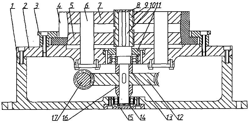
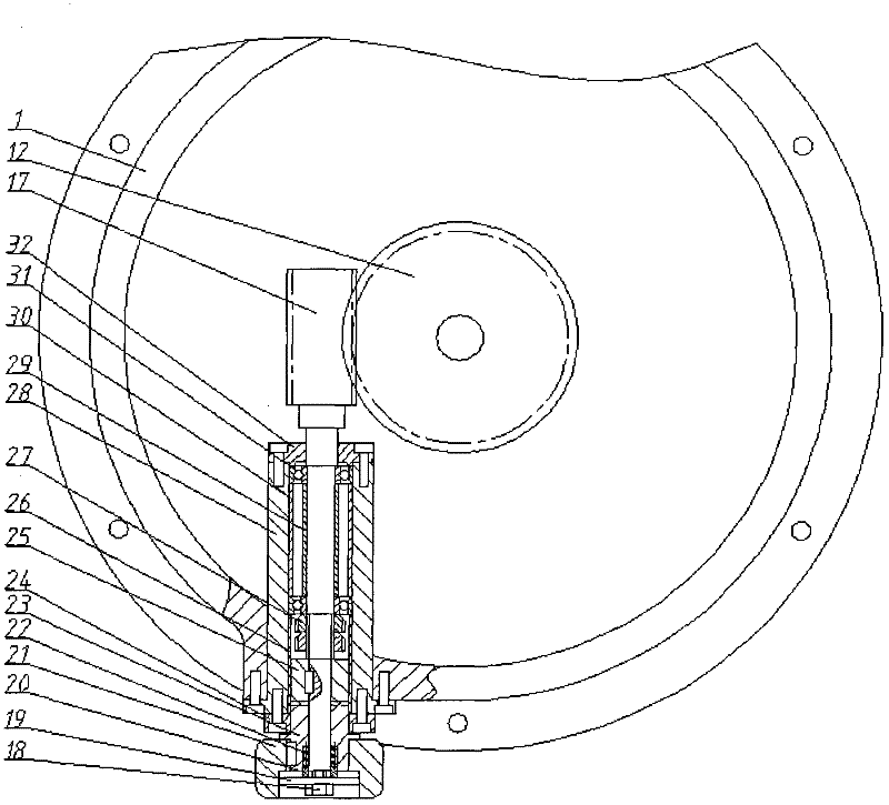
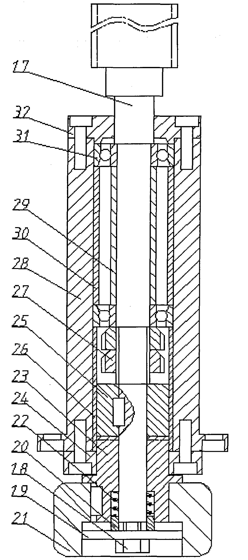
[0029] like figure 1 and figure 2 shown. This example includes a machine base 1, a machine base top cover 2, a shaft 10, a machine base end cover 11, a clamping mechanism, a feed mechanism, a transmission mechanism and a torque limiting mechanism, wherein the machine base top cover 2 is installed on the machine base 1, The base end cover 11 is located in the center hole of the base cover 2, and the bearing seat of the shaft 10 is located in the center hole of the base 1, and is fastened by the bearing end cover 15. The clamping mechanism is installed on the top cover 2 of the machine base, and the feeding mechanism is installed in the machine base 1. The clamping mechanism and the feeding mechanism respectively complete the introduction of clamping sleeve parts and external force. There is an installation platform of the transmission mechanism on the ou...


PUM


Abstract

The utility model discloses a clamp for inner support sleeve like parts. An engine seat top cap is installed on an engine base, and an engine seat end cap is positioned in a central hole of the engine seat top cap. A worm of a transmission mechanism is installed in the hole of an installation platform on the periphery of the engine seat, and is vertically matched with a worm wheel of a transmission mechanism; and a shaft penetrates through the engine seat end cap in the central hole of the engine seat top cap, one end of the shaft is positioned in a swivel nut of the transmission mechanism, and the other end of the shaft is positioned in a bearing block at the center of the engine seat. The transmission mechanism is installed in the engine seat. The worm wheel of the transmission mechanism is sleeved on the shaft; and both the first sleeve and the second sleeve of the transmission mechanism are positioned in the engine seat, and are sleeved on the shaft. The worm wheel is sleeved on the shaft, and is positioned between the first sleeve and the second sleeve. A clamping mechanism is positioned on the upper surface of the engine seat top cap, and is sleeved on the shaft. The inclined planes of the two ends of an elastic sleeve are respectively matched with the outer surfaces of a left rotation conical disc and a right rotation conical disc. A worm shaft intermittently and stably moves through a torque limit mechanism. The invention has the characteristics of simple structure, safety, reliability and convenience in use.

Description

technical field [0001] The invention relates to the field of measuring sleeve parts, in particular to a fixture for positioning and clamping the inner circle of the sleeve parts and measuring the shape of the sleeve parts. Background technique [0002] At present, there are many kinds of fixtures for socket parts, such as self-centering spring socket fixtures, back-pull socket chucks and flexible self-centering fixtures. Among them, "Metal Processing" No. 3, 2010 "Processing Thin-walled Long Tube Parts with Self-Centering Spring Sleeve Fixtures" has greatly improved the axial positioning method of the sleeve-type parts fixture, which improves the sleeve The coaxiality requirements for the clamping of such parts, but the power transmission part is still the traditional tie rod. The pull rod directly drives the spring sleeve through linear motion to control the clamping and loosening of the sleeve-type parts fixture, leaving the sleeve-type parts fixture clamp The tight buffe...

Claims


Application Information

Patent Timeline
IPC IPC(8): B25B11/00G01B21/20
Inventor 徐娅萍杨伟平谭小群孙刚峰付怀庆顾立彬陈自立
Owner NORTHWESTERN POLYTECHNICAL UNIV
Learn More