
Network intelligent control device for fire protection system

A technology of network intelligence and control devices, applied in fire alarms, instruments, fire rescue, etc., can solve problems such as fire hazards, fire equipment, facility damage, and equipment failures that cannot be detected in time, so as to prevent excessive pressure and ensure stability running effect

Inactive Publication Date: 2011-12-28
CHUANYU ELECTRICAL DANDONG CITY
View PDF5 Cites 18 Cited by
  • Summary
  • Abstract
  • Description
  • Claims
  • Application Information

AI Technical Summary

Problems solved by technology

Because the fire-fighting facilities and equipment are in a static and non-working state all year round, even if they are charged, due to the influence of corrosion, changes in temperature and humidity, dust and other natural conditions, and the quality problems of some equipment, etc., the fire-fighting equipment and facilities have also been damaged. damage
Due to the failure to find faults in time, coupled with the lack of human attention, power outages and shutdowns occur from time to time, and the equipment cannot operate continuously.
The reason is that there is a lack of management techniques, and the daily inspection, detection and maintenance cannot be in place in time, let alone the real-time tracking and monitoring, collection, archiving, and fault feedback of the equipment's operating status.
Usually relying on manual inspection and maintenance is difficult to manage in place. Even if some equipment fails, it cannot be found in time, resulting in fire-fighting facilities and equipment in an unsatisfactory state for a long time, which is likely to cause fire hazards and cause irreparable losses.

Method used


Image

  • Network intelligent control device for fire protection system
  • Network intelligent control device for fire protection system
  • Network intelligent control device for fire protection system

Examples


Embodiment Construction

[0013] The present invention will be further described below in conjunction with the accompanying drawings.

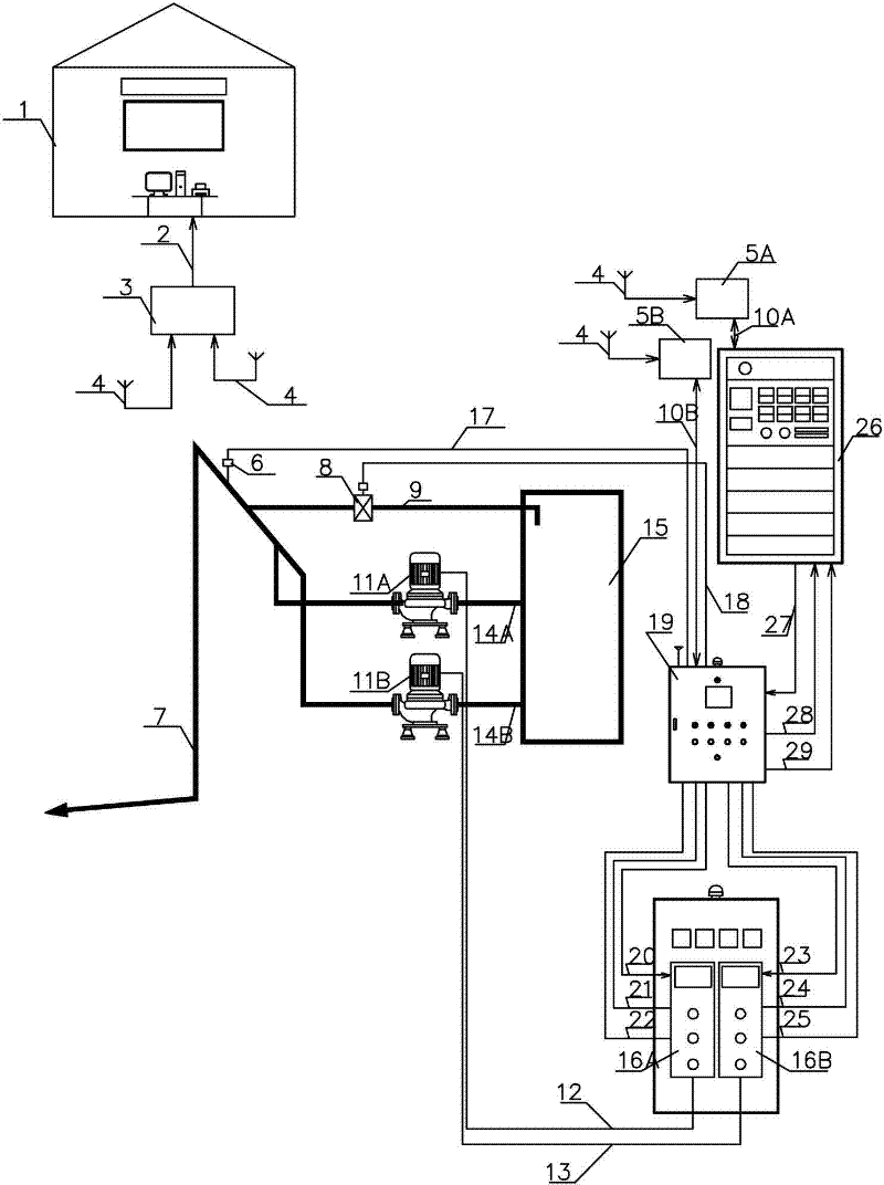
[0014]A network intelligent control device for a fire-fighting system, comprising a fire alarm linkage control cabinet 26 set on a fire-fighting pipe network, a No. Water pipe 7, drain return pipe 9, No. 1 fire pump suction pipe 14A, No. 2 fire pump suction pipe 14B, No. 1 fire pump 11A, No. 2 fire pump 11B, pressure transmitter 6 is installed at fire outlet pipe 7 , used to detect the fire outlet water pressure and control the fire system to automatically enter the firefighting state; the drain electric valve 8 is installed at the drain return pipe 9 to prevent the fire outlet water pressure from being too high during the inspection process; the fire alarm linkage control cabinet 26 passes Fire alarm linkage control cabinet startup control connection 27, fire alarm linkage control cabinet fault connection 28, fire alarm linkage control cabinet feedback connection 29 a...


PUM


Abstract

The invention relates to a fire extinguishing system network intelligent control device, which can timely track monitoring management according to the running state of a fire extinguishing system, and can record the entire running process and state so as to realize remote monitoring and remote control. The device adopts PLC (Programmable Logic Controller)to detect the water outlet pressure of thefire extinguishing system, a fire activating signal and a manual activating signal of a fire alarm linkage control cabinet to automatically control a network intelligent control cabinet to be under afire-fighting state, and to start a fire pump to run. A pressure transmitter and an electric drain valve are arranged on a fire control outlet pipe and a return pipe on a fire control pipe network, the network intelligent control cabinet is connected with the fire alarm linkage control cabinet and a fire pump control cabinet on the fire control pipe network, and a network management monitoring center is respectively connected with the fire alarm linkage control cabinet and the network intelligent control cabinet. The invention can cause the fire extinguishing system to be under an ideal state, can find a fault timely, automatically records a working state, realizes centralized monitoring and management, and has important meaning for ensuring the stable running of the fire extinguishing system.

Description

technical field [0001] The invention relates to a network intelligent control device for water supply equipment and control equipment of a fire protection system, in particular to a fire protection system that can track, monitor and manage in real time according to the operation status of the fire protection system and can completely record the operation process and status to realize remote monitoring and remote control. System network intelligent control device. Background technique [0002] At present, the water supply equipment of the known fire protection system is composed of water pump, motor, pressure water tank, pressure controller, electric control cabinet, fire alarm linkage control cabinet, instrument, pipeline and so on. Because the fire-fighting facilities and equipment are in a static and non-working state all year round, even if they are charged, due to the influence of corrosion, changes in temperature and humidity, dust and other natural conditions, and the ...

Claims


Application Information

Patent Timeline
IPC IPC(8): A62C37/00G08B17/00G08B25/00
Inventor 宋泽智徐东辉王彤侯安生宋永斌方荣张雪梅徐乃灿
Owner CHUANYU ELECTRICAL DANDONG CITY
Learn More