Fuel injection device

一种燃料、连接装置的技术,应用在燃料喷射装置、特殊燃料喷射装置、装料系统等方向,能够解决更贵等问题,达到制造成本低廉、大直径、可靠密封的效果

Inactive Publication Date: 2015-04-01
ROBERT BOSCH GMBH
View PDF7 Cites 0 Cited by
  • Summary
  • Abstract
  • Description
  • Claims
  • Application Information

AI Technical Summary

Problems solved by technology

Piezoelectric actuators, in contrast, are faster but relatively more expensive

Method used


Image

  • Fuel injection device
  • Fuel injection device
  • Fuel injection device

Examples


Embodiment Construction

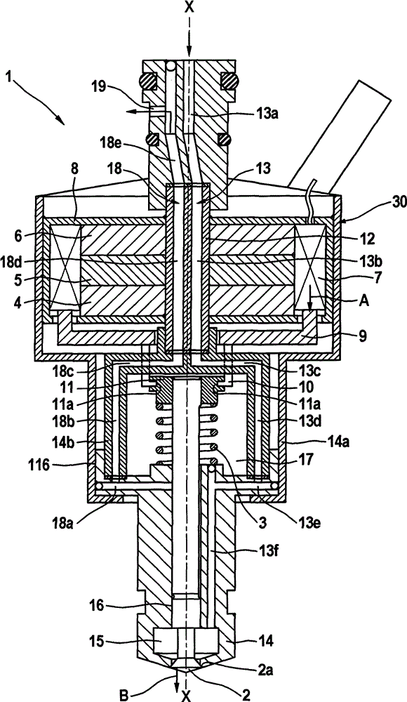
[0021] Refer below figure 1 The device 1 for injecting high-pressure fuel is described in detail.

[0022] Such as figure 1 As shown, the device 1 includes an electric actuator 30 , a needle 2 , a fuel supply pipe 13 , and a fuel return pipe 18 , wherein high-pressure fuel is supplied in the fuel supply pipe 13 and low-pressure fuel is returned in the fuel return pipe 18 . The electric actuator 30 includes a first permanent magnet 4 , a second permanent magnet 6 , and an intermediate disk 5 . The intermediate disk 5 is made of magnetically permeable material and is arranged between the first permanent magnet 4 and the second permanent magnet 6 . The electric actuator 30 also comprises a movably arranged coil 7 arranged on the outer circumference of the first and second permanent magnets 4 , 6 and of the intermediate disk 5 . The outer cover 8 is made of magnetically permeable material and surrounds the coil 7 and the end walls of the first permanent magnet 4 and the second ...


PUM


Abstract

A device for injecting pressurized fuel includes an electrodynamic actuator having a movably situated coil, an outwardly opening needle which opens and closes a cross section on a valve seat, a connecting device which connects the needle to the movably situated coil, a pressure chamber which is situated at the needle upstream from the valve seat and contains pressurized fuel, a low-pressure chamber from which, fuel is dischargeable, and a gap seal which is provided at an outer peripheral region of the needle, the gap seal (16) providing a connection between the pressure chamber and the low-pressure chamber.

Description

technical field [0001] The invention relates to a fuel injection device in which, in particular, fuel under pressure is injected into a combustion chamber of an internal combustion engine. Background technique [0002] Fuel injection devices are known for injecting fuel, for example in motor vehicle engines. In addition, diesel fuel injection has recently also injected Otto fuel. Frequently, for fuel injection, here the fuel is supplied from a reservoir (rail) and injected via an injection device into the combustion chamber or into the suction pipe. Here, on the one hand, electromagnetic actuators or alternatively piezoelectric actuators are used as actuators. Electromagnetic actuators are relatively inexpensive here, but also relatively slow. Piezoelectric actuators, in contrast, are faster but relatively more expensive. Accordingly, it would be desirable to have a spraying device with a relatively fast yet inexpensive actuator. Contents of the invention [0003] The...

Claims


Application Information

Patent Timeline
Patent Type & Authority Patents(China)
IPC IPC(8): F02M51/06H01F7/06F02M61/10F02M63/00
CPCF02M51/0682F02M51/0696F02M2200/707H01F7/066
Inventor J·格拉纳M·迈尔M·许贝尔G·霍尔
Owner ROBERT BOSCH GMBH
Why Eureka
Try Eureka