LED anti-flash circuit

An anti-flicker, circuit technology, applied in the layout of electric lamp circuits, electric light sources, lighting devices, etc., can solve the problems of slow discharge speed and uncomfortable feeling.

Active Publication Date: 2014-03-12
SELF ELECTRONICS CO LTD
View PDF4 Cites 0 Cited by
  • Summary
  • Abstract
  • Description
  • Claims
  • Application Information

AI Technical Summary

Problems solved by technology

Another solution is to add an auxiliary power supply system to the first-level AC / DC module, and the dimming signal generation circuit is powered by the auxiliary power supply system, so that the no-load power consumption will reach a relatively low state (<0.5W), but due to the first The capacity of the filter capacitor C1 output by the first-stage AC / DC module is relatively large, which is several times larger than the capacity of the filter capacitor C2 of the power supply system of the dimming signal generating circuit. DC module), the discharge speed of C1 is slower than that of C2. When the load is small and the light is dimmed to the darkest, the LED light is relatively dim due to the relatively small current, and the output voltage is also low. At this time When C2 discharges to O, the dimming signal disappears, and the DC / DC module returns to the normal working mode. At this time, the voltage on C1 is still very high, and it is higher than the minimum power supply voltage of the DC / DC chip, then the LED will turn on again. It is broken down, working in normal state, and the brightness must be brighter than the dimmest one. Although the time is very short, but from the phenomenon, it will flicker once or several times when it is turned off. feel very uncomfortable

Method used


Image

  • LED anti-flash circuit
  • LED anti-flash circuit

Examples


Embodiment 1

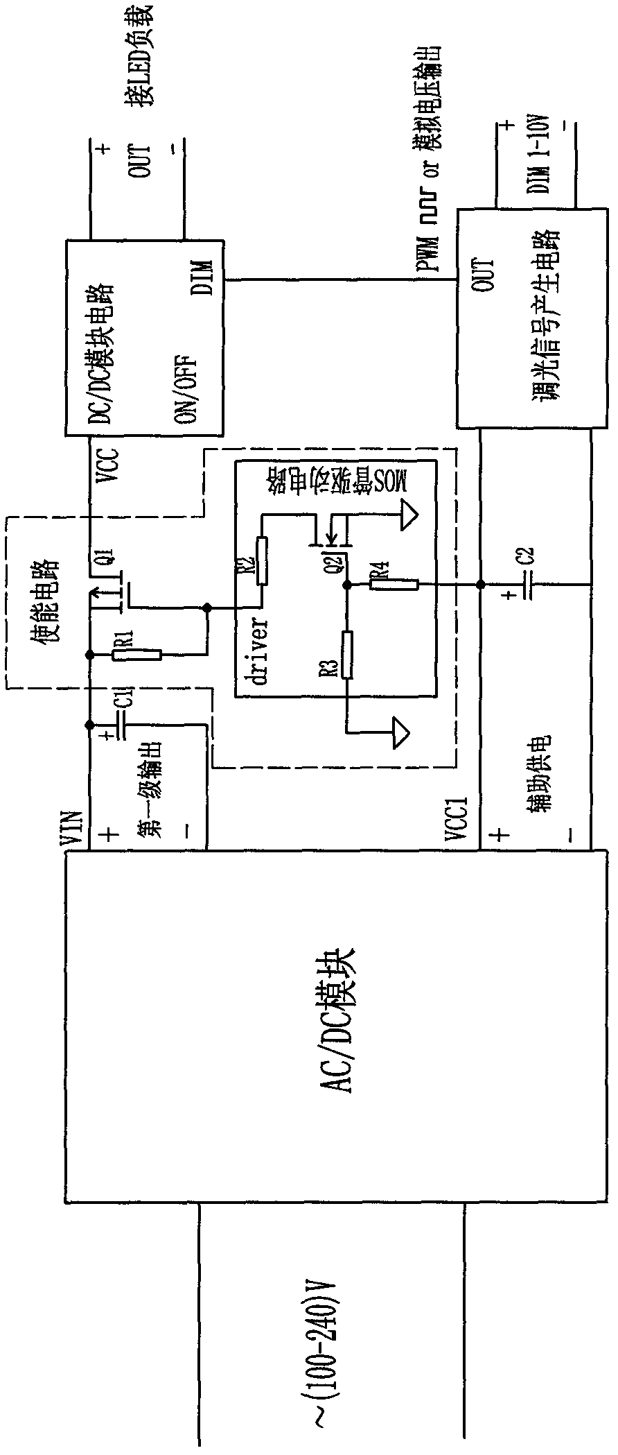
[0016] see figure 1 The LED anti-flicker circuit shown includes AC / DC module, DC / DC module, dimming signal generation circuit, first capacitor C1, second capacitor C2 and used to control the working state of DC / DC module, and when AC / DC When the input power of the module is turned off, the enabling circuit of the DC / DC module power supply can be forcibly turned off. The input terminal of the AC / DC module is connected to the external mains power supply, and the two ends of the first capacitor C1 are respectively connected to the main power supply of the AC / DC module. The two output terminals VIN+ / - of the terminal are connected, the two ends of the second capacitor C2 are respectively connected with the two output terminals VCC1+ / - of the auxiliary power supply terminal of the AC / DC module, and the two input terminals of the dimming signal generating circuit are respectively connected with the second capacitor C2. The two ends are connected, the output terminal OUT of the dimmi...

Embodiment 2

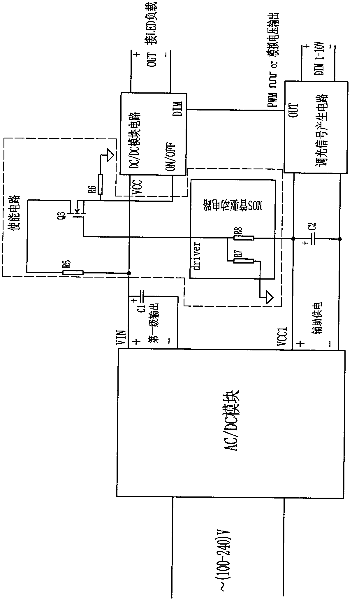
[0021] The difference from Embodiment 1 is that the enabling circuit includes an N-type field effect transistor Q3, a MOS transistor drive circuit, a fifth resistor R5 and a sixth resistor R6, wherein the input terminal of the MOS transistor drive circuit is connected to the AC / DC module The positive output terminal of the auxiliary power supply is connected, the output terminal of the MOS transistor drive circuit is connected to the gate of the N-type field effect transistor Q3, and the drain of the N-type field effect transistor Q3 is connected to the positive electrode of the first capacitor after connecting the fifth resistor R5 The source of the N-type field effect transistor Q3 is connected to the sixth resistor R6 and then grounded, and the source of the N-type field effect transistor is also connected to the ON / OFF pin of the DC / DC module; the power input terminal of the DC / DC module is connected to the The positive electrode of the first capacitor is connected to each ...


PUM


Abstract

The invention relates to an LED anti-flash circuit which comprises an AC / DC module, a DC / DC module, a light-adjusting signal generation circuit, a first capacitor and a second capacitor; wherein the input end of the AC / DC module is connected with the external commercial power, two ends of the first capacitor are respectively connected with two output ends of the main power supply end of the AC / DC module, two ends of the second capacitor are respectively connected with two output ends of the auxiliary power supply end of the AC / DC module, two input ends of the light-adjusting signal generation circuit are respectively connected with two ends of the second capacitor, and the output end of the light-adjusting signal generation circuit is connected with the light-adjusting interface end of the DC / DC module, and the output end of the DC / DC module is connected with the LED load; the circuit is characterized by also comprising an enable circuit which is used for controlling the working mode of the DC / DC module and enforcedly shutting the power supply of the DC / DC module when the input power supply of the AC / DC module is switched off, the input end of the enable circuit is connected at two ends of the first capacitor, and the output end of the enable circuit is connected with the output end of the DC / DC module. Compared with the prior art, the circuit can thoroughly solve the flash phenomenon occurred when the LED power supply is switched off.

Description

technical field [0001] The invention relates to an LED anti-flicker circuit, in particular to a two-stage dimming power supply using an AC / DC module as the first stage and a DC / DC module as the second stage as the LED driving power supply. When the input power supply is turned off, Circuit to prevent LED flickering. Background technique [0002] The existing LED dimming technology is mainly divided into two categories from the principle of dimming signal generation: one is analog dimming, the other is PWM dimming, both of which require additional circuit modules to achieve, which requires additional power supply circuits support. Among the commonly used two-stage dimming power supplies that use the first stage as an AC / DC module and the second stage uses a DC / DC module, the first stage in front is an AC / DC module, which is used to generate a constant voltage source. This voltage source is used as a DC The power supply voltage of the / DC module, the DC / DC module of the seco...

Claims


Application Information

Patent Timeline
Patent Type & Authority Patents(China)
IPC IPC(8): H05B37/02
Inventor 吴其志汪彪林万炯
Owner SELF ELECTRONICS CO LTD
Why Eureka
Try Eureka