
Manufacturing method of electrical connector

A manufacturing method and technology of electrical connectors, applied in the direction of contact manufacturing, connection, assembly/disassembly of contact parts, etc., can solve the problems of complex processing and manufacturing, high cost, complicated conductive terminals, etc., and achieve simple processing and manufacturing and low cost , The effect of reducing manufacturing costs

Active Publication Date: 2011-12-14
DEYI PRECISION ELECTRONIC IND CO LTD PANYU
View PDF4 Cites 7 Cited by
  • Summary
  • Abstract
  • Description
  • Claims
  • Application Information

AI Technical Summary

Problems solved by technology

Its technical defect is: when the structure of the conductive terminal is complicated, the structure of the receiving hole will also become complicated correspondingly in order to match the conductive terminal. For example, the width of the receiving hole should be greater than or equal to that of the conductive terminal. The width of the conductive terminal can be installed in the receiving hole
The manufacturing of the conductive terminals and the insulating body is complicated and costly, which increases the manufacturing cost of the electrical connector, and makes the arrangement density of the conductive terminals in the insulating body relatively small, which is not conducive to the The Development of Miniaturization of Electrical Connectors

Method used


Image

  • Manufacturing method of electrical connector
  • Manufacturing method of electrical connector
  • Manufacturing method of electrical connector

Examples


Embodiment Construction

[0024] The manufacturing method of the electrical connector of the present invention will be further described below with reference to the drawings and specific embodiments.

[0025] The manufacturing method of electrical connector of the present invention has following steps:

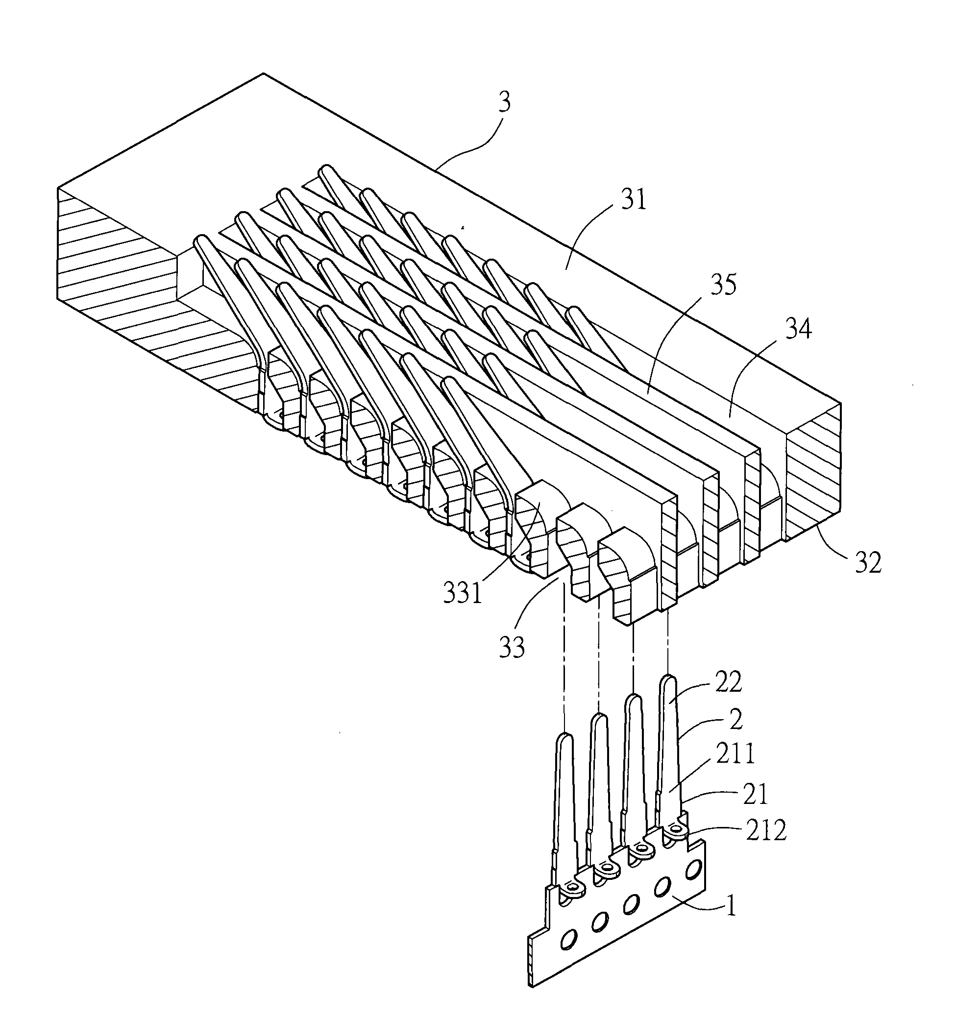
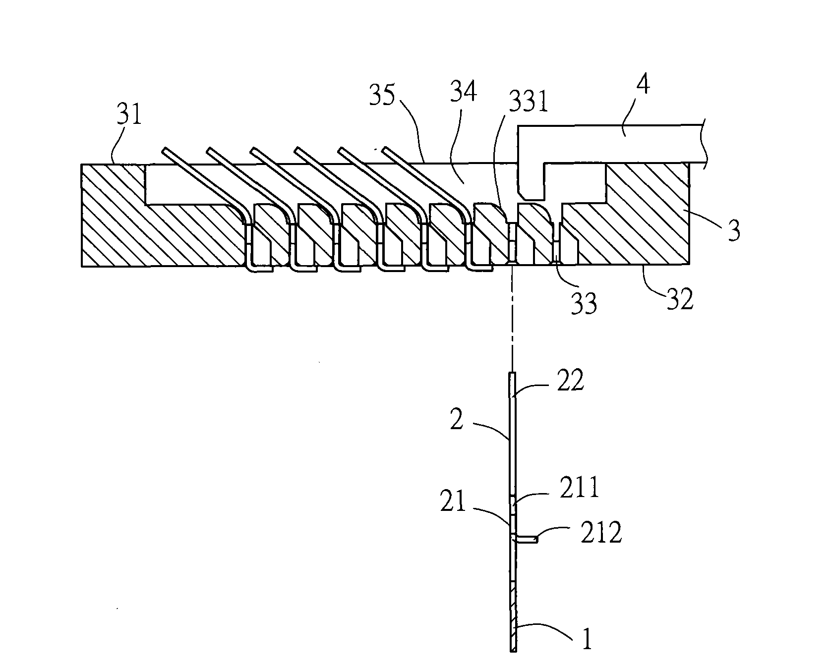
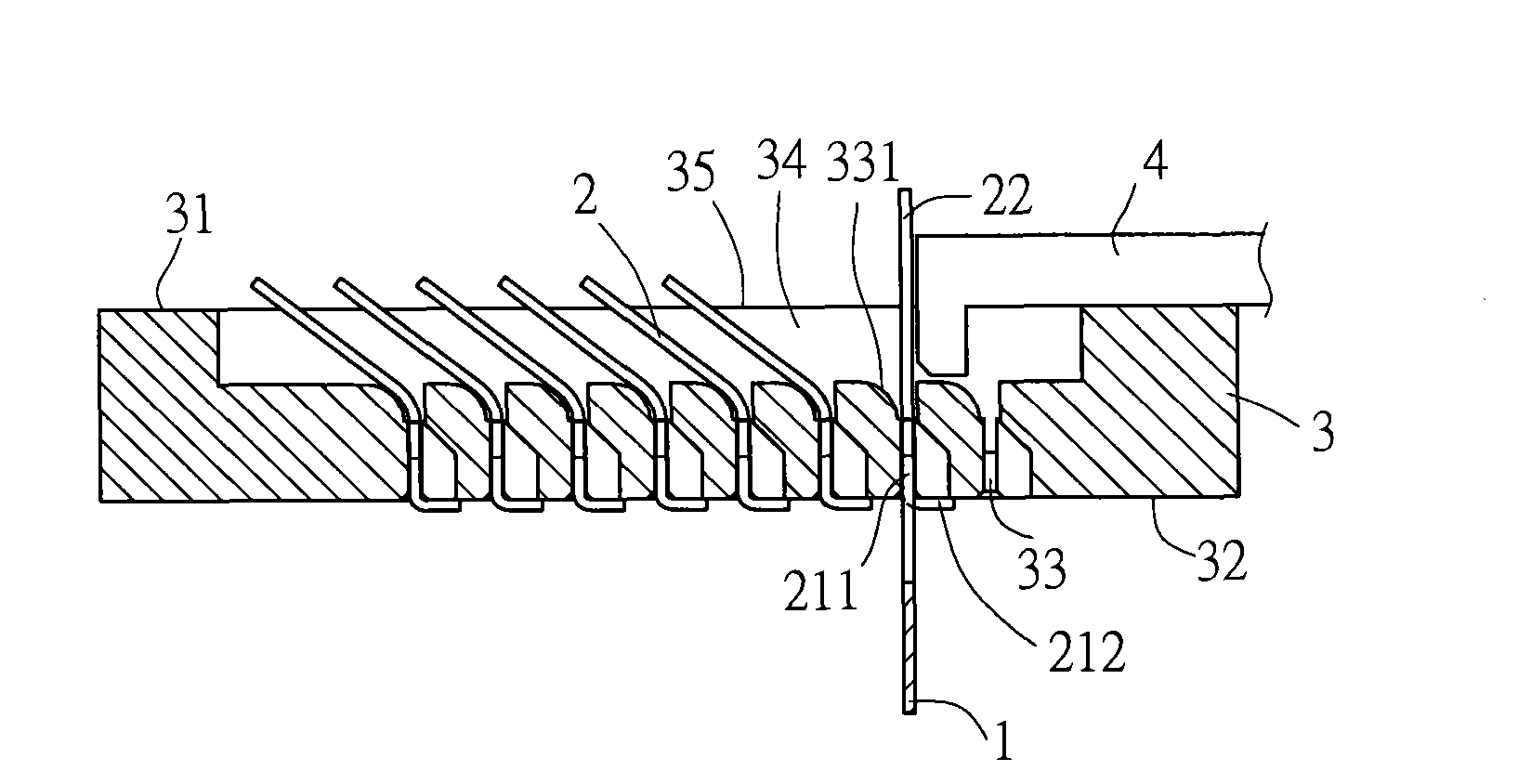
[0026] A sheet metal (not shown) is provided, see figure 1 , forming a strip 1 and a plurality of terminals 2 arranged on the strip 1 at intervals by punching and blanking. Each of the terminals 2 has a fixing portion 21 and an extension arm 22 extending from the fixing portion 21 . The strip 1 is connected to the fixing portion 21 of each terminal 2 .

[0027] The end of the fixing portion 21 of each terminal 2 is bent to form a welding portion 212 , and the connection between the welding portion 212 and the extension arm 22 is defined as a base portion 211 . The strip 1 is connected to the base portion 211 of each terminal 2 (of course, in other embodiments, the strip 1 can also be connected to th...


PUM


Abstract

The invention provides a manufacturing method of an electric connector, which comprises the following steps of: providing a metal plate, and forming at least one strip and a plurality of terminals through stamping and blanking, wherein the plurality of terminals are arranged on the strip at intervals, each terminal is provided with a fixing part and an extension arm extending from the fixing part, and the strip is connected with the fixing part of each terminal; moving the strip to correspond to the bottom surface of an insulation body, so that the extension arm of each arranged terminal corresponds to corresponding row of accommodating holes of the insulation body; moving the strip towards the direction close to the bottom surface of the insulation body, so that the extension arm of eachterminal exposes out of the top surface of each accommodating hole through the accommodating hole and the fixing part of each terminal is fixed in the accommodating hole; providing a jig for pressingall the terminals, wherein the extension arm of each terminal is bent laterally, so that the length of a projection of the extension arm in the horizontal direction is greater than the width of each accommodating hole; and cutting off the strips connected with all the terminals. According to the invention, all the terminals installed into the insulation body are pressed by using the jig, which isbeneficial to realizing of the small-spacing arrangement of the terminals in the insulation body.

Description

【Technical field】 [0001] The invention relates to a method for manufacturing an electrical connector, in particular to a method for manufacturing a high-density electrical connector. 【Background technique】 [0002] It is called an electrical connector for electrically connecting two electronic components. The electrical connector generally includes an insulating body with a plurality of receiving holes and a plurality of conductive terminals correspondingly located in the receiving holes. In order to ensure The performance of the conductive terminal is good in terms of elasticity and life, and the conductive terminal is generally formed by punching and bending multiple metal plates to ensure the above-mentioned good performance. [0003] In order to form the electrical connector, one of the commonly used manufacturing methods in the industry is: first place a plurality of the conductive terminals after punching and forming in a mold, then inject a liquid insulating material ...

Claims


Application Information

Patent Timeline
Patent Type & Authority Applications(China)
IPC IPC(8): H01R43/00H01R43/20H01R43/16
Inventor 王刚
Owner DEYI PRECISION ELECTRONIC IND CO LTD PANYU
Learn More