
A circular waveguide te01 mode converter

A mode conversion and circular waveguide technology, which is applied in the field of circular waveguide TE01 mode mode converters, can solve the problems of high mode purity and narrow working bandwidth, and achieve the effects of high mode purity, wide working bandwidth and reduced insertion loss.

Inactive Publication Date: 2011-12-14
INST OF ELECTRONICS ENG CHINA ACAD OF ENG PHYSICS
View PDF1 Cites 18 Cited by
  • Summary
  • Abstract
  • Description
  • Claims
  • Application Information

AI Technical Summary

Problems solved by technology

The side coupling method is mainly through opening coupling holes on the smooth waveguide wall. The typical coupling method is porous directional coupling. The side coupling mode converter is usually characterized by high mode purity but relatively narrow operating bandwidth.

Method used


Image

  • A circular waveguide te01 mode converter
  • A circular waveguide te01 mode converter
  • A circular waveguide te01 mode converter

Examples


Embodiment 1

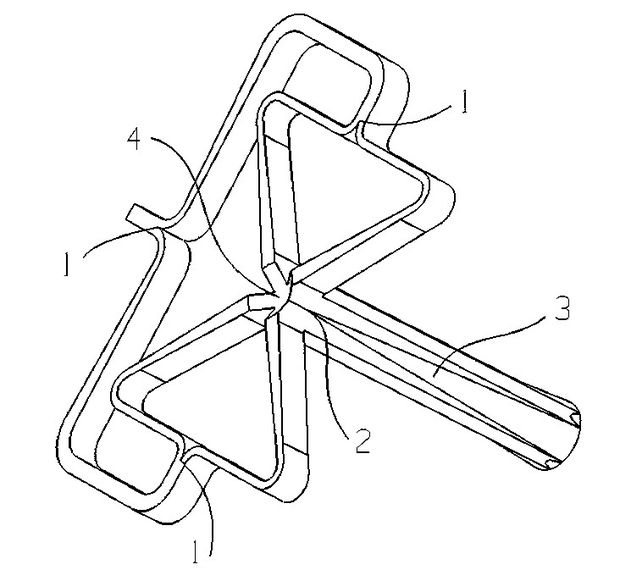
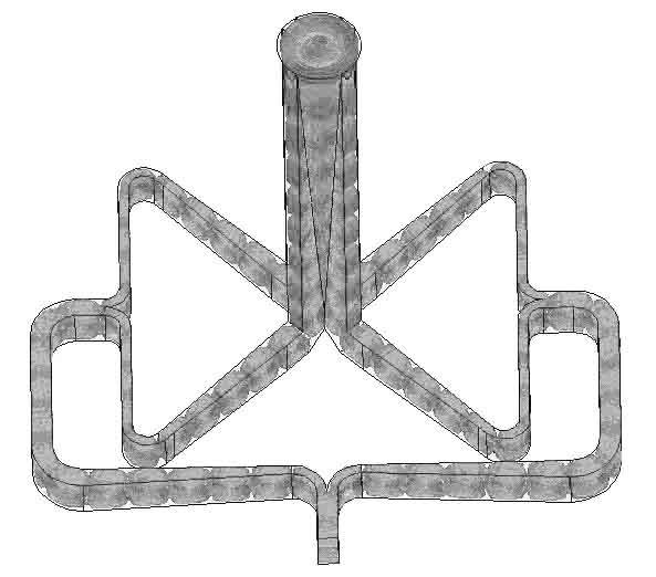
[0025] like Figure 1-2 As shown, the present invention is a circular waveguide TE 01 The mode-mode converter includes a rectangular waveguide power division structure unit, a mode conversion structure unit and a waveguide gradient structure unit, the rectangular waveguide power division structure unit and the mode conversion structure unit are in the same plane, the four output waveguides of the rectangular waveguide power division structure unit and the The cross-shaped waveguide structure of the mode conversion structural unit is vertically connected; the output end of the mode conversion structural unit is a cross-shaped waveguide, and the waveguide gradual change structural unit is to gradually change the cross-shaped waveguide to a circular waveguide, and the method is to build a conical gradient along the central axis of the cross-shaped waveguide The waveguide realizes that the output port is a circular waveguide.

[0026] Among them, the specific structure is as foll...


PUM


Abstract

The invention discloses a circular waveguide TE01 mode mode converter, which comprises a rectangular waveguide power division structure unit, a mode conversion structure unit and a waveguide gradient structure unit, the rectangular waveguide power division structure unit is connected with the mode conversion structure unit, and the mode conversion structure unit is connected with the mode conversion structure unit The waveguide gradient structure unit is connected; when the rectangular waveguide power division structure unit includes a two-level branch waveguide structure, the electromagnetic wave TE10 mode first enters through the rectangular waveguide power division structure unit, and forms two channels of equal amplitude power division through the two first-level branch waveguide structures. TE10 modes with equal amplitude and phase, and then two channels of TE10 modes with equal amplitude and phase are divided into four channels of TE10 modes with equal amplitude and phase through the second-stage branch waveguide structure. The structure unit is converted, and after the conversion, the circular waveguide is obtained through the waveguide gradual change structure unit and the TE01 mode is output; the invention has the advantages of high mode purity, wide working bandwidth and easy processing.

Description

technical field [0001] The invention relates to a circular waveguide TE in the field of communication technology 01 mode technology, in particular a circular waveguide TE 01 mode converter. Background technique [0002] Circular waveguide TE 01 The mold has a circular symmetric structure of electric field and magnetic field and low waveguide loss characteristics, so it has important applications in many fields, such as electronic gyrotron devices, gyrotrons, millimeter wave long-distance transmission and other fields. In particular, the gyrotron device requires an efficient mode converter, and its stability and tunability are directly affected by the performance of the mode converter. [0003] In the prior art, the circular waveguide TE 01 Mode methods are roughly divided into direct coupling and side coupling. The method of direct coupling is usually to convert the input waveguide mode into the desired mode by changing the waveguide structure. The mode converter using ...

Claims


Application Information

Patent Timeline
IPC IPC(8): H01P1/163
Inventor 王永帅蔡钟斌康小克刘玥玲郑贵强肖红伟
Owner INST OF ELECTRONICS ENG CHINA ACAD OF ENG PHYSICS
Learn More