
Wire rope plug-in device

A technology of plug-in device and steel wire rope, which is applied in auxiliary devices for rope making, textiles and papermaking, textile cables, etc. It can solve problems affecting construction quality, looseness, and damage to galvanized layers, so as to reduce physical labor intensity and make The effect of standardizing the process and improving work efficiency

Inactive Publication Date: 2011-12-14
DANGSHAN POWER SUPPLY ANHUI ELECTRIC POWER CORP
View PDF6 Cites 4 Cited by
  • Summary
  • Abstract
  • Description
  • Claims
  • Application Information

AI Technical Summary

Problems solved by technology

In the current process of making wire rope sleeves, it is often necessary for the staff to repeat the same action with wrist strength for a long time. Inserting a qualified wire rope sleeve or ring rope needs to repeat the same action 30 times, which takes 45 minutes. During the production process, The palms of the hands holding screwdrivers, hammers and other tools are particularly prone to wear and injury, and are injured by being smashed. It takes time and effort. If you encounter a steel wire rope with a large diameter, it is easy to break the steel wire, and it is easy to break the wire and damage the galvanized layer. Gap, not tight, affecting construction quality

Method used


Image

  • Wire rope plug-in device
  • Wire rope plug-in device
  • Wire rope plug-in device

Examples


Embodiment

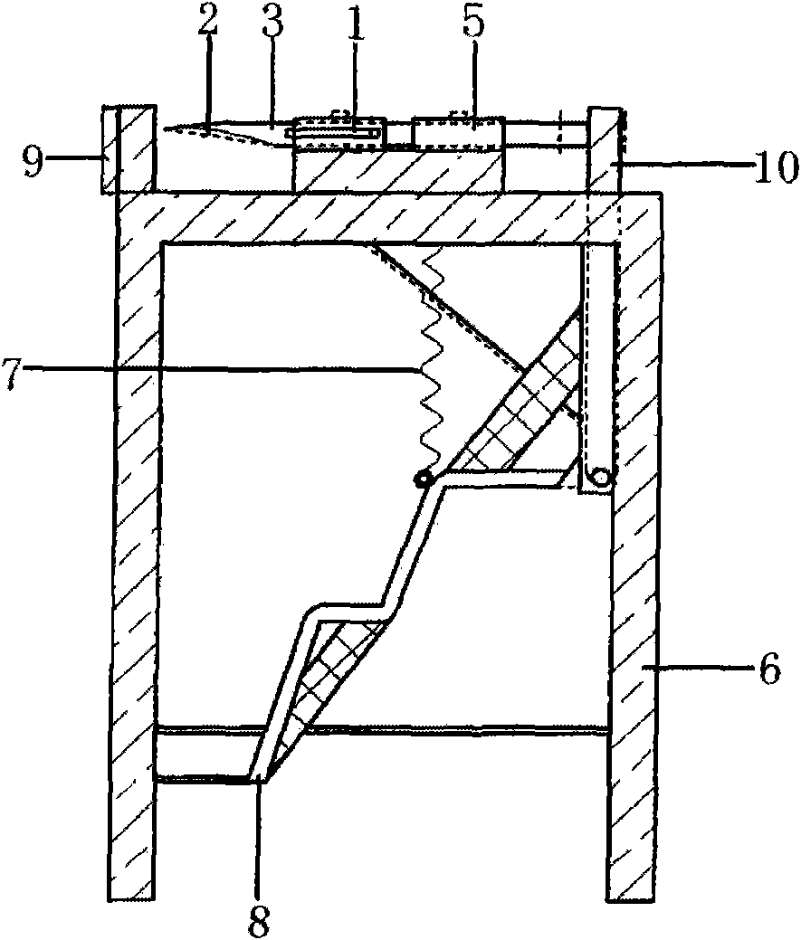
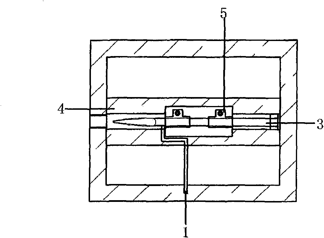
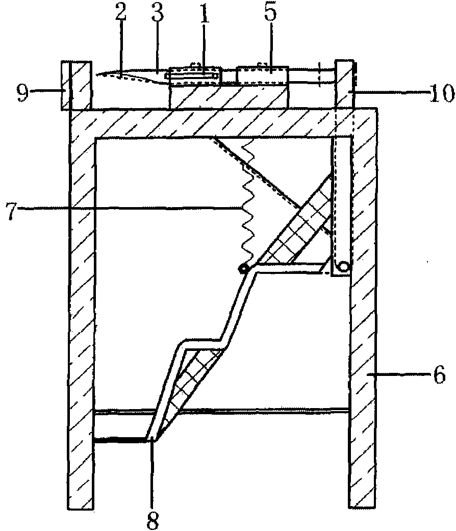
[0009] Embodiment: The device is composed of an operating handle 1, an introduction groove 2, a needle threading 3, a guide rail 4, a fixing clip 5, a bracket 6, a spring 7, a pedal 8, a baffle plate 9, and a push rod 10. The threading needle 3 is fixed by The clamp 5 is fixed on the guide rail 4 of the bracket 6, the side of the needle 3 has an operating handle 1, the needle of the needle 3 has an introduction groove 2, the tail end of the needle 3 is stuck on the upper end of the ejector rod 10, and the lower end of the ejector rod 10 is connected to the Foot pedal 8 is also fixed on the support 6, and spring 8 is arranged between foot pedal 8 and guide rail 4, and the needle of threading needle 3 is to the gap of two baffle plates 9 on the support 6.

[0010] The device uses angle steel to cut and weld to make bracket 6. The upper end of bracket 6 is polished with round steel to make needle 3 and weld operation handle 1 on the side of needle 3. Fix clip 5 to fix on bracket 6...


PUM


Abstract

A wire rope plugging device, which is composed of an operating handle, an introduction slot, a threading needle, a guide rail, a fixed clip, a bracket, a spring, a pedal, a baffle, and an ejector rod. The threaded needle is fixed on the guide rail of the bracket through the fixed clip, There is an operating handle on one side of the needle, and there is an introduction groove on the needle head for threading the needle. The end of the threading needle is stuck on the upper end of the ejector rod, and the lower end of the ejector rod is connected to the pedal and fixed on the bracket. There is a spring between the pedal and the guide rail. The gap between the needle of the needle and the two baffles on the support. This device prevents the wire rope from being broken and the galvanized layer from being damaged; the mechanical lever principle of the foot pedal makes it easier to thread the needle into the wire rope, and the strength and angle of insertion can be precisely controlled, effectively reducing the intensity of physical labor ; It only takes 12 minutes to insert a 20mm diameter wire rope cover with this device, which greatly improves the work efficiency and reduces the labor intensity, and is especially suitable for mass production of standardized rope sets and ring ropes.

Description

technical field [0001] The invention relates to a wire rope device for hoisting in electric power construction. Background technique [0002] At present, steel wire ropes are indispensable slings for lifting, traction, binding, temporary stays, etc. in the construction of power transmission lines. set of situations. The insertion method of the steel wire rope ring rope and the rope sleeve used for lifting in electric power construction is to use a hammer to smash a screwdriver into the steel wire strands by hand, use the screwdriver to pry open the steel wire strands and leave a gap, so that the rope head can penetrate into the gap between the steel wire strands , and finally pull out the screwdriver forcefully, so as to complete the insertion of a rope end. In the current process of making wire rope sleeves, it is often necessary for the staff to repeat the same action with wrist strength for a long time. Inserting a qualified wire rope sleeve or ring rope needs to repeat...

Claims


Application Information

Patent Timeline
Patent Type & Authority Applications(China)
IPC IPC(8): D07B7/14
Inventor 朱继军乔冬郭芳雄
Owner DANGSHAN POWER SUPPLY ANHUI ELECTRIC POWER CORP
Learn More