
Breathing tube control valve and gas pipeline for connecting the control valve

A gas pipeline and control valve technology, applied in the field of medical equipment, can solve problems such as inconvenience, pipeline cut or cut, large pressure difference between inside and outside of the valve plate, etc., to reduce noise and solve problems and inconvenience.

Inactive Publication Date: 2011-12-14
SMITHS MEDICAL INT +1
View PDF7 Cites 11 Cited by
  • Summary
  • Abstract
  • Description
  • Claims
  • Application Information

AI Technical Summary

Problems solved by technology

[0002] The breathing tube control valve generally used to supply oxygen to patients. In the existing design, it is used to measure whether the pressure value in the breathing tube is normal. The pressure line is a gas line connected by the control valve. One side is externally connected; when the pressure pipeline is connected externally between the breathing tube control valve and the ventilator, it is easy to cause inconvenience and troubles due to the external winding of the pipeline, especially if the pipeline is exposed. The risk of being cut or cut off by an external sharp knife will cause the pressure tube to fail to measure the pressure value in the breathing tube normally, which will be related to whether the ventilator can provide enough oxygen for the patient, thus indirectly affecting the patient safety of life
[0003] In addition, the existing breathing tube control valve often has problems such as excessive pressure difference between the inside and outside of the valve, which also causes noise from the valve.

Method used


Image

  • Breathing tube control valve and gas pipeline for connecting the control valve
  • Breathing tube control valve and gas pipeline for connecting the control valve
  • Breathing tube control valve and gas pipeline for connecting the control valve

Examples


Embodiment Construction

[0034] In order to further understand the features and technical contents of the present invention, please refer to the following detailed description and drawings related to the present invention, but the attached drawings are only for reference and illustration, and are not intended to limit the present invention.

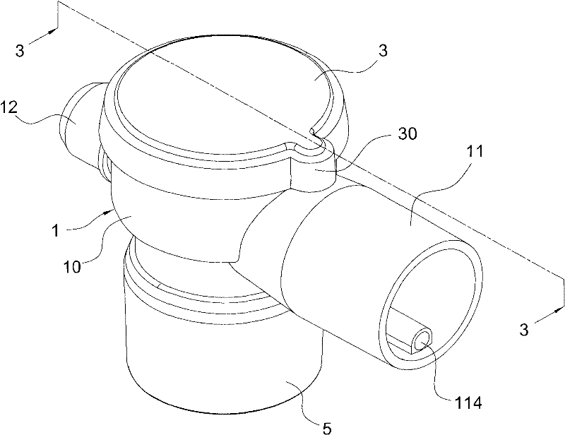
[0035] see figure 1 , figure 2 and image 3 , are respectively the three-dimensional exploded view, the three-dimensional combined view and the present invention figure 2 3-3 section cutaway view. The present invention provides a breathing tube control valve and a gas pipeline for connecting the control valve. The breathing tube control valve includes a housing 1, a valve part 2, and a cover 3; wherein:

[0036] The housing 1 is hollow, and has a cavity pipe 10, an air inlet pipe 11 and an air outlet pipe 12, and an inner pipe 100 is arranged in the chamber pipe 10, and an inner cavity 101 is formed in the inner pipe 100, which is connected with the air inle...


PUM


Abstract

A breathing tube control valve and a gas pipeline for connecting the control valve, the control valve includes a housing, a valve part and a cover, the housing has a cavity, an air inlet pipe and an air outlet pipe, the cavity There is an inner tube inside the tube, which forms an inner cavity and communicates with the air inlet and outlet pipes. The valve part is set on the cavity tube, and the cover is closed on the valve part; wherein, the air inlet pipe of the shell is provided with a A pressure pipe joint with a small diameter leading to the inner cavity is used to connect a pressure pipeline, and the gas pipeline is used to connect with an air inlet pipe so that the pressure pipeline is built into the gas pipeline. In this way, the existing pressure pipeline installed externally can be changed to be installed in the same direction in the intake pipe pipeline, and the trouble and inconvenience caused by the externally connected type can be avoided in a built-in way.

Description

technical field [0001] The invention relates to a medical device, in particular to a breathing tube control valve and a gas pipeline used for supplying oxygen to patients. Background technique [0002] The breathing tube control valve generally used to supply oxygen to patients. In the existing design, it is used to measure whether the pressure value in the breathing tube is normal. The pressure line is a gas line connected by the control valve. One side is externally connected; when the pressure pipeline is connected externally between the breathing tube control valve and the ventilator, it is easy to cause inconvenience and troubles due to the external winding of the pipeline, especially if the pipeline is exposed. The risk of being cut or cut off by an external sharp knife will cause the pressure tube to fail to measure the pressure value in the breathing tube normally, which will be related to whether the ventilator can provide enough oxygen for the patient, thus indirec...

Claims


Application Information

Patent Timeline
IPC IPC(8): A61M16/20A61M16/00A61M16/08
Inventor 保罗・詹姆士・莱斯利・贝南特杨千朋
Owner SMITHS MEDICAL INT
Learn More