
A Configurable Differential Delay Cell Circuit

A unit circuit and differential delay technology, which is applied in the field of differential delay unit circuit structure, can solve the problems of output frequency adjustment range limitation, large design overhead, no multiplexing ability, etc., and achieve area cost reduction, area reduction, and implementation selectivity Effect

Inactive Publication Date: 2011-12-07
NAT UNIV OF DEFENSE TECH
View PDF5 Cites 3 Cited by
  • Summary
  • Abstract
  • Description
  • Claims
  • Application Information

AI Technical Summary

Problems solved by technology

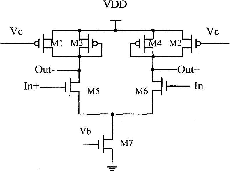
[0003] 1. figure 1 As shown in the conventional differential delay unit, the input signal port is fixed and has no multiplexing capability, and the loop formed thereby lacks sufficient flexibility;
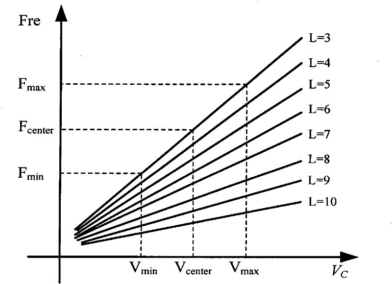
[0004] 2. For ring oscillators composed of conventional differential delay units, the number of delay unit stages is usually fixed. When the gain of the VCO is low, the adjustment range of the output frequency is limited;
[0005] 3. The variable ring oscillator composed of conventional differential delay units requires a large number of delay units and a large design overhead. Figure 4 The structure in is taken as an example. Since the conventional differential delay unit cannot be multiplexed, to realize an oscillator with delay unit stages of 3, 4, 5, 6, 7, 8, 9 and 10, it is necessary to form 8 oscillation loops respectively. A total of 52 delay units are required
[0006] The root cause of the above problems is that the delay units forming the loop cannot be reused

Method used


Image

  • A Configurable Differential Delay Cell Circuit
  • A Configurable Differential Delay Cell Circuit
  • A Configurable Differential Delay Cell Circuit

Examples


Embodiment Construction

[0019] The circuit structure and working process of the configurable differential delay unit disclosed in the present invention will be described in detail below in conjunction with the accompanying drawings.

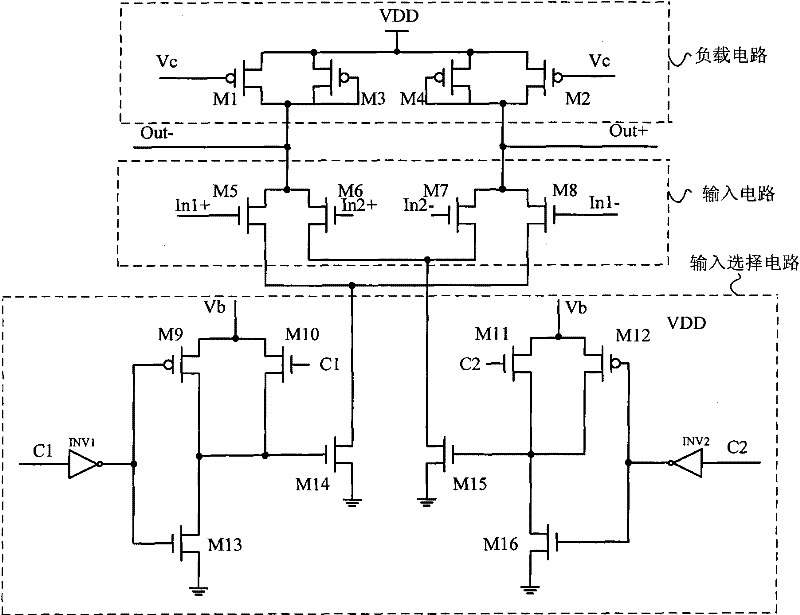
[0020] The invention discloses a configurable differential delay unit circuit, which is characterized in that it includes an input selection circuit, an input circuit and a load circuit, specifically composed of PMOS transistors M1, M2, M3, M4, M9, M12, NOMS transistors M5, M6 , M7, M8, M10, M11, M13, M14, M15, M16 and inverters INV1, INV2; the specific feature is that: M5 and M8 form a source coupling pair of tubes, and their gates are respectively connected to differential inputs In1+ and In1- , its drains are respectively connected to the differential outputs Out- and Out+, its source is connected to the drain of M14, the source of M14 is connected to ground, its gate is connected to the source of M10, the drain of M13 and the drain of M9 , the drain of M10 is connec...


PUM


Abstract

The invention discloses a differential delay unit circuit which has a configurable property and is applied to variable-loop voltage-controlled oscillators. Delay units can change signal propagation paths under the control of an input selecting circuit, and the mode based on multiplexing the delay units changes the stage number of the delay units in the loop, so as to form a configurable annular oscillator with the lowest expenditure, provide different types of gains to voltage-controlled oscillators and increase the range of adjustment. The configurable differential delay unit circuit disclosed by the invention comprises an input selecting circuit, an input circuit and a load circuit.

Description

technical field [0001] The invention belongs to the field of integrated circuit design and is applied to the design of voltage-controlled oscillators, in particular to a configurable differential delay unit circuit structure. Background technique [0002] A voltage-controlled oscillator (Voltage-controlled Oscillator, VCO) is widely used in various integrated circuits. As a kind of voltage-controlled oscillator, the ring voltage-controlled oscillator is favored by designers because of its simple structure, small area cost and easy integration. In a phase-locked loop circuit, the output frequency is usually adjusted by changing the control voltage Vc, and the ratio of the VCO output frequency range to the Vc adjustment range is called the VCO gain. If the VCO gain is high, it is easy to introduce noise in the phase-locked loop; conversely, if the VCO gain is low, it may reduce the frequency range of the phase-locked loop and prolong the locking time. Therefore, PLL noise, f...

Claims


Application Information

Patent Timeline
IPC IPC(8): H03L7/099
Inventor 李少青段志奎赵振宇张民选郭阳陈吉华马卓张明郑涛孙岩何小威乐大珩谭晓强张均安
Owner NAT UNIV OF DEFENSE TECH
Learn More