
proportional valve

A proportional valve and valve body technology, applied in the field of proportional valves, can solve the problems of complex structure of the proportional valve actuator, insufficient anti-interference ability, staying in the scheme design, etc., and achieve the effects of simple structure, good sealing performance and stable control process.

Inactive Publication Date: 2011-12-07
BEIJING AEONMED
View PDF5 Cites 3 Cited by
  • Summary
  • Abstract
  • Description
  • Claims
  • Application Information

AI Technical Summary

Problems solved by technology

[0002] In the current engineering applications, most of the proportional valve actuators have complex structures, low stability, insufficient anti-interference ability, and more importantly, low machinability. Some can only stay in the scheme design and are difficult to realize.

Method used


Image

  • proportional valve
  • proportional valve
  • proportional valve

Examples


no. 1 example

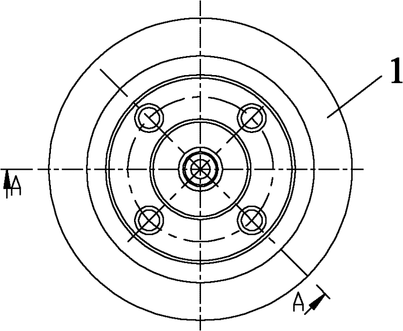
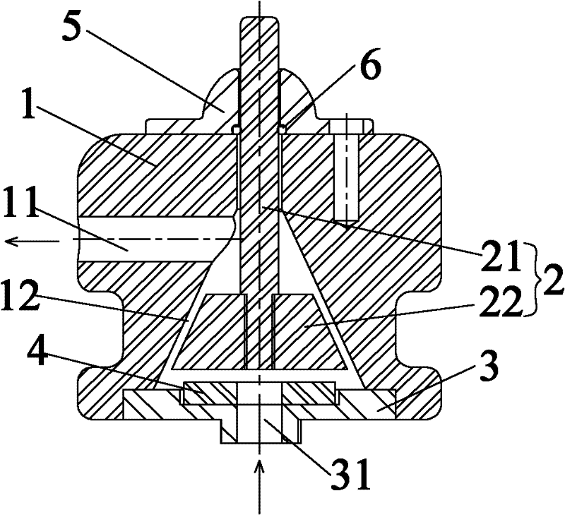
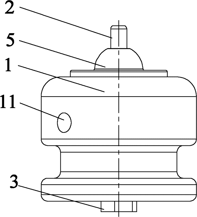
[0021] Such as figure 1 with figure 2 As shown, according to the first embodiment of the present invention, the proportional valve includes a valve body 1 and a valve core 2 disposed in the cavity 12 of the valve body 1 , and the valve core 2 and the valve body 1 are fitted with a conical surface. The valve core 2 includes a cone core 22 with a conical surface and a slide rod 21 fixedly connected with the cone core 22 and slidably arranged in the valve body 1 . A seal ring 6 is provided at the joint between the protruding end of the slide rod 21 and the upper end of the valve body 1, and a gland 5 fixedly connected to the valve body 1 is arranged outside the seal ring 6, and the gland 5 presses the seal ring 6 tightly against the valve body. The joint between the upper end of the body 1 and the slide rod 1 keeps the entire valve body in good airtightness. There is clearance fit between the slide rod 21 and the valve body 1 , and the valve core 2 is suspended in the cavity o...


PUM


Abstract

The invention provides a proportional valve. The proportional valve comprises a valve body (1) and a valve core (2) arranged in a cavity (12) of the valve body (1), and the valve core (2) and the valve body (1) are matched by a conical surface. The proportional valve according to the invention has the advantages of flexible mechanism, stable precision, high controllability, lightness and durability, and can realize precise control and self-centering.

Description

technical field [0001] The invention relates to the field of flow control, in particular to a proportional valve. Background technique [0002] In the current engineering applications, most of the proportional valve actuators have complex structures, low stability, insufficient anti-interference ability, and more importantly, low machinability. Some of them can only stay in the scheme design and are difficult to realize. Contents of the invention [0003] The present invention aims to provide a proportional valve, which has the advantages of flexible mechanism, stable precision, high controllability, lightness and durability, and can realize precise control and self-centering. [0004] In order to achieve the above object, the present invention provides a proportional valve, which includes a valve body and a valve core arranged in the cavity of the valve body, and the valve core and the valve body are fitted by a tapered surface. [0005] Further, the valve core includes ...

Claims


Application Information

Patent Timeline
Patent Type & Authority Applications(China)
IPC IPC(8): F16K1/38F16K1/48F16K41/04F16K31/06
Inventor 东志翔
Owner BEIJING AEONMED
Learn More