Anti-seepage stop valve

A cut-off valve and anti-leakage technology, applied in the direction of lift valves, valve devices, engine components, etc., can solve the problems of easy leakage and waste of water resources at the joint between the valve core and the valve stem, and achieve simple and reasonable structure and easy installation And the effect of easy disassembly and preventing shaking

Inactive Publication Date: 2014-07-16
ANHUI KANGJIA PLASTIC BUILDING MATERIAL
View PDF0 Cites 0 Cited by
  • Summary
  • Abstract
  • Description
  • Claims
  • Application Information

AI Technical Summary

Problems solved by technology

The problem brought by this fixing method is that the joint between the valve core and the valve stem is prone to leakage, resulting in a large waste of water resources.

Method used


Image

  • Anti-seepage stop valve
  • Anti-seepage stop valve
  • Anti-seepage stop valve

Examples


Embodiment Construction

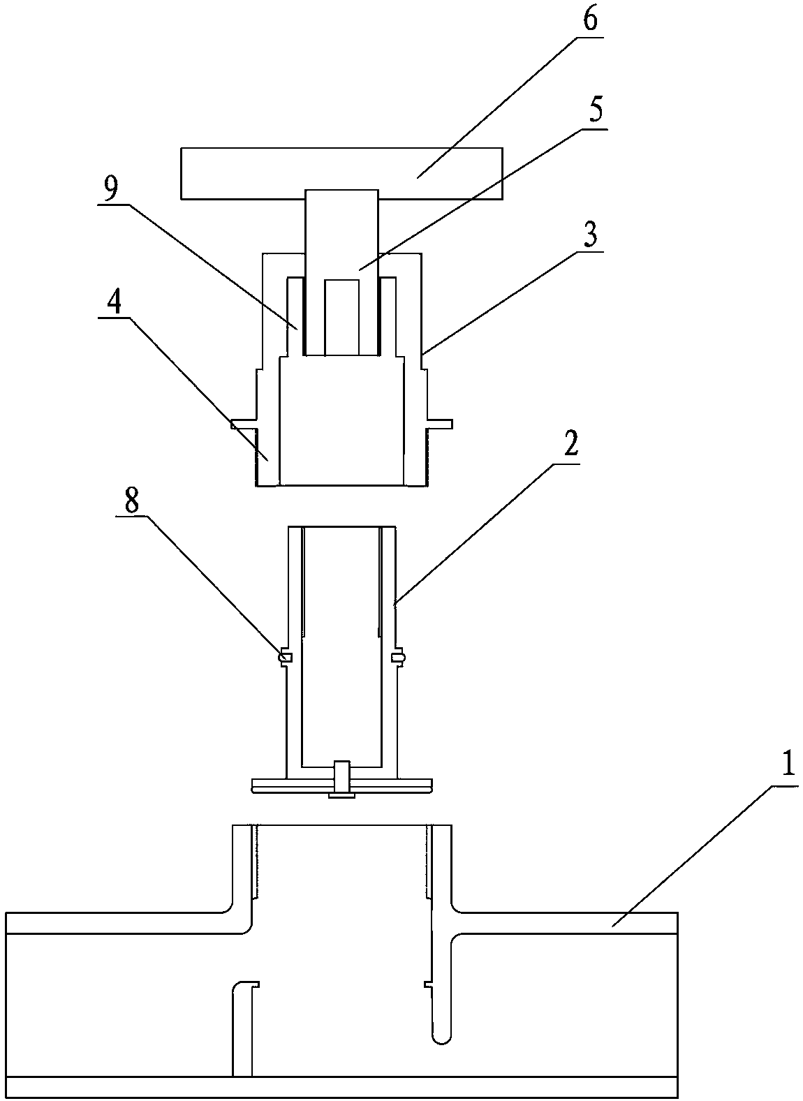
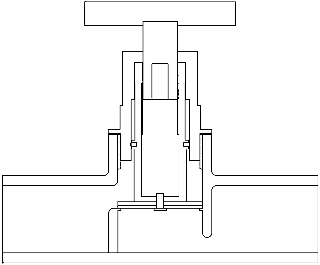
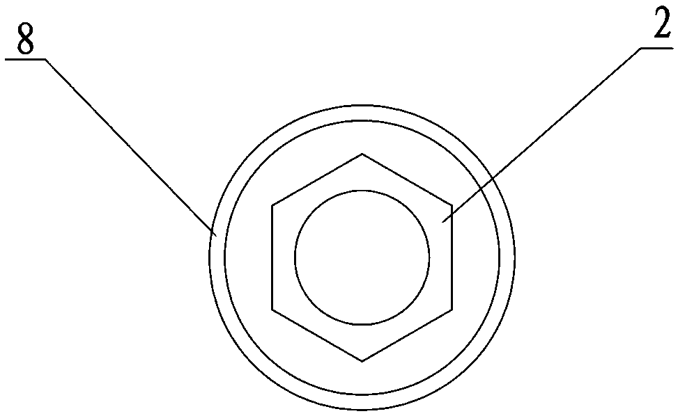
[0012] Refer to 1 and 2, an anti-leakage stop valve, including a valve body 1, a valve core 2 and a valve stem 3, the lower part of the valve stem 3 is connected to the upper part of the valve core 2 through threads, and the center of the upper end surface of the valve core 2 is provided with an axial thread Blind hole; the lower part of the valve stem 3 is provided with a sleeve 4, and the outer surface of the sleeve 4 is provided with threads for connecting with the valve body 1; The rotary handle 6 is connected, and the lower part of the screw rod 5 is used to spirally cooperate with the axial threaded hole on the valve core 2; the outer surface of the valve core 2 is provided with an annular rib 7, and at least one annular rib 7 is provided on the outer surface of the annular rib 7. Groove, a sealing ring 8 is placed in the annular groove, which is used to form a water seal between the valve core 2 and the inner wall of the valve stem sleeve 4 . The effect of sealing ring ...


PUM


Abstract

The invention relates to a stop valve, in particular to an anti-seepage stop valve. The anti-seepage stop valve comprises a valve body, a valve element and a valve rod. The lower portion of the valve rod is connected with the upper portion of the valve element through threads. An axial threaded blind hole is formed in the center of the upper end face of the valve element. The lower portion of the valve rod is provided with a sleeve. Threads are arranged on the outer surface of the sleeve and used for being connected with the valve body. A screw capable of rotating is arranged in the middle of an inner cavity of the valve rod. The upper portion of the screw is connected with a rotary handle of the stop valve. The lower portion of the screw is used for being matched with the axial threaded hole of the valve element in a threaded mode. An annular protruding edge is arranged on the outer circular face of the valve element. At least one annular groove is formed in the outer circular face of the annular protruding edge. A sealing ring is placed in the annular groove and used for generating a water seal between the valve element and the inner wall of the sleeve of the valve rod. Compared with the prior art, the anti-seepage stop valve has the advantages that the seal between the valve element and the inner wall of the valve rod is kept through the sealing ring, so that water pressure is reduced, and therefore the anti-seepage effect is finally achieved.

Description

technical field [0001] The invention relates to a shut-off valve, in particular to an anti-leakage shut-off valve. Background technique [0002] The spool and valve stem of the valves sold and used in the market are threaded on the valve stem, and the coupling hole on the spool is a through hole, which is fixed with a nut after assembly. The problem brought by such a fixing method is that the joint between the valve core and the valve stem is prone to leakage, resulting in a large waste of water resources. Contents of the invention [0003] In order to overcome the disadvantages of the prior art, the present invention provides an anti-leakage stop valve with simple and reasonable structure and convenient installation and disassembly, so that the joint between the valve core and the valve stem no longer leaks. [0004] The technical solution adopted in the present invention is: an anti-leakage stop valve, including a valve body, a valve core and a valve stem. There is an ...

Claims


Application Information

Patent Timeline
IPC IPC(8): F16K1/00F16K1/32F16K1/36
CPCF16K1/04F16K1/36F16K1/46F16K1/48
Inventor 林超庞善金
Owner ANHUI KANGJIA PLASTIC BUILDING MATERIAL
Why Eureka
Try Eureka