Electrical implementation unit having a conical contact surface engaging a conical borehole formed in a housing of an electrical component

a technology of electrical components and conical contact surfaces, which is applied in the direction of electrical equipment, dynamo-electric machines, supports/enclosements/casings, etc., can solve the problems of requiring additional space, gtms requires more space for assembly, and limited freely accessible area for installing gtms, so as to improve the pressure resistance and stiffness of the motor housing, save assembly time and assembly expense, and assemble

Active Publication Date: 2018-10-09
HANON SYST
View PDF16 Cites 2 Cited by
  • Summary
  • Abstract
  • Description
  • Claims
  • Application Information

AI Technical Summary

Benefits of technology

[0021]Due to advantageous self-centering of the pins during the assembly process due to the wedge shape, narrow positional tolerances result, which has a positive effect on the quality of the assembly. Also an advantage is that, due to the compact design of the invention-specific electrical feed-through unit, the electrical feed-through unit can be easily accessible within the housing of an electric motor. Additionally, the electrical feed-through unit can be assembled independently of the assembly of the stator of the electric motor, resulting in assembly time being optimized. In other words, the electrical feed-through units and the stator of the electric motor can be inserted in the same assembly step, since the electrical feed-through units are easily accessible and not covered by the stator during the assembly process. Due to free accessibility, it is possible for stator windings to then make contact with the pins. It is also conceivable that the pins can be pre-assembled with the windings of the stator. An option is offered of combined assembly operation, requiring no subsequent assembly step.
[0037]Due to simplified application and low price, the concept can also be of interest for semi-hermetic or non-hermetic applications. If the thermal and pressure requirements are low, Duromer can be replaced by a thermoplastic or elastomer.

Problems solved by technology

If the stator is already installed in the motor housing, only a limited freely-accessible area remains for installing the GTMS.
However, as a rule, the GTMS requires more space for assembly.
For this reason, electrical feed-through units are often placed outside the motor diameter, which requires additional room for the application and increases the overall structural space of the engine housing.
This results in a difficult assembly operation or in a blind operations when the stator winding then makes contact with the GTMS.
A further disadvantage of the known GTMS are the large apertures required in the housing, which contribute to a weakening of the overall structure, which is especially relevant in high-pressure applications such as a carbon dioxide compressor.
Additionally, the difficult GTMS manufacturing process results in higher tolerances of electrically conducting pins.
Along with that, the manufacturing process and also the later application places limits on choices for material of the current-carrying line to steel, which does not have good electrical properties.
Lastly, due to brittleness of glass, GTMS is very sensitive to mechanical effects such as shear forces or torsion, which may appear during the assembly process.

Method used


Image

  • Electrical implementation unit having a conical contact surface engaging a conical borehole formed in a housing of an electrical component
  • Electrical implementation unit having a conical contact surface engaging a conical borehole formed in a housing of an electrical component
  • Electrical implementation unit having a conical contact surface engaging a conical borehole formed in a housing of an electrical component

Examples


Embodiment Construction

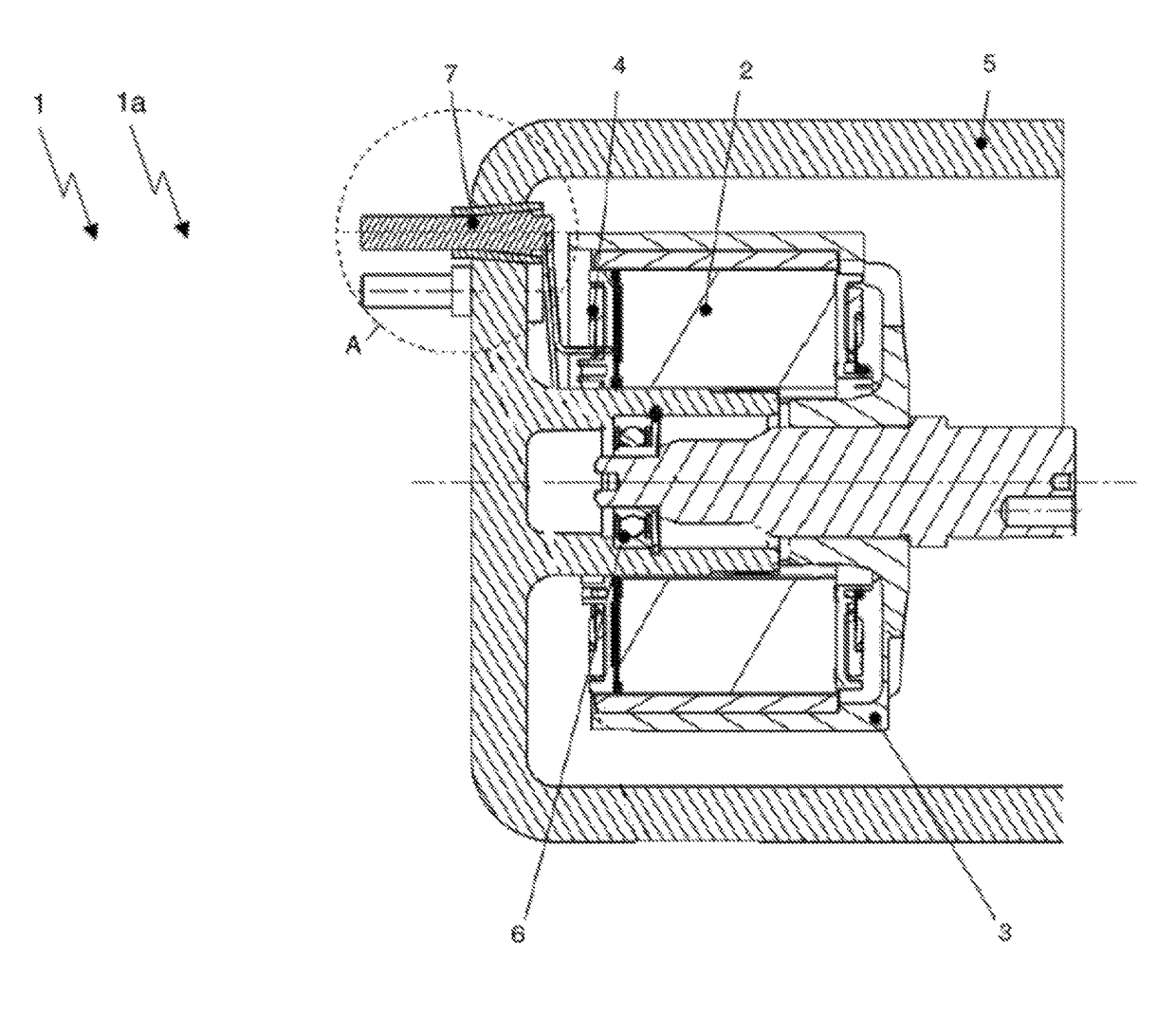
[0049]FIG. 1 shows a brushless electric motor 1. Here in the version of an exterior runner motor 1a. Here the stator 2 is located within the rotor 3, which surrounds the stator. The electrical control device is attached to the stator windings 4. This exterior runner motor 1a is suitable for hermetically sealed applications and is surrounded by a gas-tight housing 5. The motor bearing 6 is also situated within the stator 2. For contacting the electric motor 1 externally, on housing 5, an electrical feed-through unit 7 is situated. The electrical feed-through unit 7 is inserted with a wedge shape into housing 5. The section A indicates the area of electrical feed-through unit 7 in housing 5.

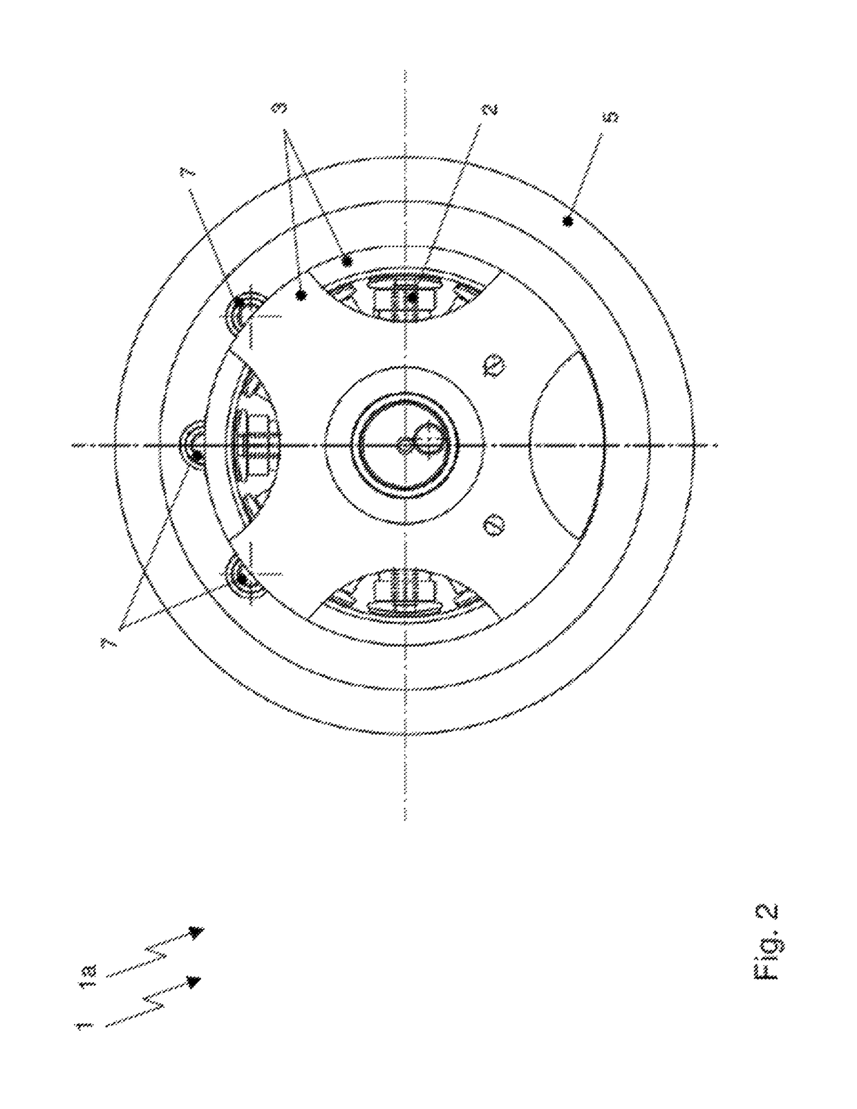
[0050]FIG. 2 shows a rear view of the exterior runner motor 1a from FIG. 1. The elements of stator 2 are partially covered by the rotor. Also the electrical feed-through units 7 are only perceived in a partial fashion. The motor 1 is in a hermetically sealed housing 5.

[0051]FIG. 3 shows the arrange...


PUM

PropertyMeasurementUnit
shapeaaaaaaaaaa
electrically conductingaaaaaaaaaa
pressureaaaaaaaaaa

Abstract

The invention relates to an electrical feed-through unit for penetration of electrical contacts through the wall of a housing of an electric motor. It has a pin made of an electrically conducting material, which is surrounded by an electrically insulating material. The pin possesses an at least partially wedge-shaped contact surface for the area of a penetration through the wall of the housing and is able to be arranged with the sheath surrounding it in an at least partially wedge-shaped borehole penetrating through the wall of the housing. In addition, the invention relates to a housing of an electric motor, which contains at least one such electrical feed-through unit as well as an electric motor which has such a housing.What is advantageous with the design of an electric motor proposed here, is that, through savings in assembly time and assembly expense, as well as parts costs, it is possible to assemble the motor components in the motor housing very simply and favorably, and additionally a number of advantages are offered as compared to use of conventional glass-to-metal feed-through (GTMS). The openings in the motor housing required for the electrical feed-through units are small, resulting in improved pressure resistance and stiffness of the motor housing. The cross-sectional surface to be sealed is also small, and as a consequence, the rates of leakage and permeation are low.

Description

CROSS-REFERENCES TO RELATED APPLICATIONS[0001]This application claims priority to German Patent Application No. 10 2015 103053.5, filed on Mar. 3, 2015, the disclosure of which is incorporated herein by reference in its entirety.FIELD OF THE INVENTION[0002]The invention relates to an electrical feed-through unit for feeding through of electrical contacts through the wall of a housing of an electric motor. The feed-through unit has a pin, which consists of an electrically-conducting material, and a sheath surrounding it. In addition the invention relates to the housing of an electric motor, which contains at least one such electrical feed-through unit, as well as an electric motor which has such a housing.BACKGROUND OF THE INVENTION[0003]Electrical motors for hermetical-sealing applications require a feed-through unit which directs electrical energy from the surroundings into the interior of a hermetically sealed motor housing. The feed-through unit must in this regard be sealed gas-...

Claims


Application Information

Patent Timeline
Patent Type & Authority Patents(United States)
IPC IPC(8): H02K5/22H01B17/30
CPCH01B17/301H02K5/225
Inventor GUNTERMANN, BERNDROOKS, ERICGOEBBELS, BERNADETTE
Owner HANON SYST
Why Eureka
Try Eureka