Mainstay Turbocharger Electronically Controlled Pressure Relief Valve

A technology for turbochargers and pressure relief valves, applied in valve details, valve devices, machines/engines, etc., can solve problems such as prone to surge, easy to generate airflow noise, and reduced speed-up performance and comfort, so as to avoid Effects of supercharger surge

Inactive Publication Date: 2011-12-07
HUNAN TYEN MACHINERY
View PDF4 Cites 6 Cited by
  • Summary
  • Abstract
  • Description
  • Claims
  • Application Information

AI Technical Summary

Problems solved by technology

[0004] 1. When the engine decelerates rapidly at the middle and high speed operating points, the throttle valve is closed, and the opening of the mechanical pressure relief valve requires a relatively high pressure value before it can be fully opened. When the valve is not fully opened, intake noise will be generated, which is easy Surge occurs, whistling occurs
[0005] 2. When the engine speeds up after rapid deceleration, due to the delayed response of the mechanical pressure relief valve, the valve cannot be closed in time, causing the compressor characteristics of the turbocharger to not be restored in time, and the instantaneous response is poor. Reduced speed-up performance and comfort

Method used


Image

  • Mainstay Turbocharger Electronically Controlled Pressure Relief Valve
  • Mainstay Turbocharger Electronically Controlled Pressure Relief Valve
  • Mainstay Turbocharger Electronically Controlled Pressure Relief Valve

Examples


Embodiment Construction

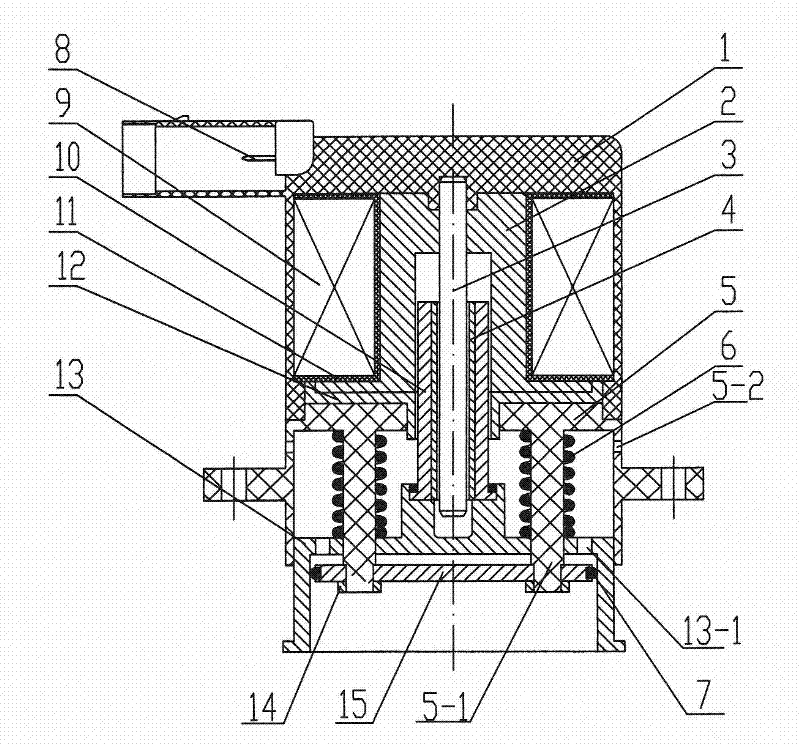
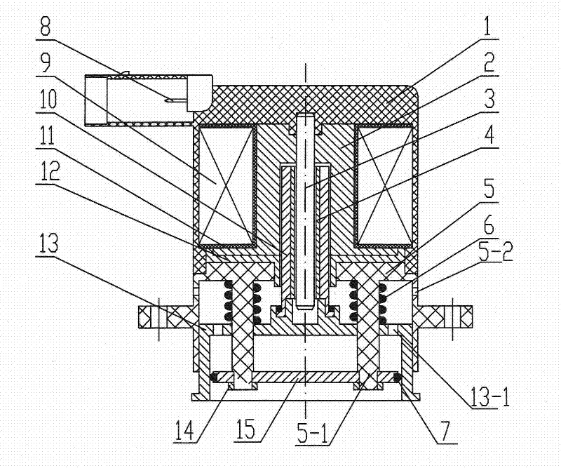
[0022] A mainstay type turbocharger electronically controlled pressure relief valve, which consists of an upper casing 1 with an electronically controlled socket 8, a guide seat 2, a static iron core 3, a moving iron core inner shaft sleeve 4, and a lower casing 5 , spring 6, sealing ring 7, coil winding frame 11 with coil winding 9, moving iron core 10, moving iron core outer shaft sleeve 12, piston sleeve 13, nut 14, baffle plate 15 are formed.

[0023] The outer shaft sleeve 12 of the moving iron core, the coil winding frame 11 with the coil winding 9, and the guide seat 2 are inlaid in the upper casing 1 by injection molding; the piston sleeve 13 is inlaid on the moving iron core 10 by injection molding, and the inner shaft of the moving iron core The sleeve 4 is press-fitted in the shaft hole of the moving iron core 10; the upper shell 1 is set on the lower shell 5, and is connected with the lower shell 5 to form an interference fit; the static iron core 3 is a round bar, ...


PUM


Abstract

A mainstay type turbocharger electronically controlled pressure relief valve, the outer shaft sleeve of the moving iron core, the coil winding frame with the coil winding, and the guide seat are inlaid in the upper casing by injection molding, and the piston sleeve is inlaid in the moving body by injection molding. on the core. The inner shaft sleeve of the moving iron core is press-fitted in the shaft hole of the moving iron core, and the upper casing is set on the lower casing, and is connected with the lower casing by an interference fit. The static iron core is press-fitted in the shaft hole of the guide seat, the moving iron core is sleeved on the static iron core, and the outer circle of the moving iron core adopts dynamic fit with the shaft hole on the outer shaft sleeve of the moving iron core. The circumference of the lower casing is provided with two symmetrically distributed pressure relief holes, and the piston hole of the lower casing is provided with two guide columns, each of which is provided with a spring, and the baffle plate is installed on the guide columns through nuts. The sealing ring is installed in the annular groove on the outer circle of the baffle, and is in contact with the inner hole wall of the piston sleeve to play a sealing role. The piston sleeve inlaid on the moving iron core is installed in the piston hole of the lower casing, and two symmetrically distributed pressure relief holes are arranged at the end of the piston sleeve.

Description

technical field [0001] The invention relates to the technical field of engine turbochargers, in particular to an electronically controlled pressure relief valve used on a volute of an engine turbocharger compressor. Background technique [0002] A supercharged engine with a throttle, especially a gasoline engine that uses supercharging technology to work, when the accelerator pedal is suddenly released, a near-closed gap will suddenly form between the outlet of the turbocharger compressor and the throttle. Volume, while the impeller in the compressor still sends compressed air into the intake pipe due to the effect of rotational inertia. At this time, the outlet pressure of the compressor rises and the air flow decreases, which easily causes the turbocharger to surge. The current solution is to use a pressure relief valve installed on the volute of the compressor to control the return flow of compressed air, so as to avoid the surge of the supercharger caused by excessive c...

Claims


Application Information

Patent Timeline
Patent Type & Authority Applications(China)
IPC IPC(8): F02B37/16F16K31/06
CPCY02T10/144Y02T10/12
Inventor 胡辽平凌泓张爱明周铮
Owner HUNAN TYEN MACHINERY
Why Eureka
Try Eureka