
Network Bottleneck Detection Method

A bottleneck detection and network technology, applied in the network field, can solve the problems of not actually applying the network, ignoring the key role of network nodes, and unable to truly reflect network bottlenecks.

Inactive Publication Date: 2011-11-30
BEIJING UNIV OF POSTS & TELECOMM
View PDF6 Cites 16 Cited by
  • Summary
  • Abstract
  • Description
  • Claims
  • Application Information

AI Technical Summary

Problems solved by technology

This causes an inevitable network load on the network, which not only affects the operation of the network, but also causes deviations in the measurement results, which cannot truly reflect the network bottleneck situation.
[0019] (2) Poor real-time performance
Long measurement duration will directly affect the real-time performance of measurement results
[0021] 2. Problems with packet loss rate bottleneck detection technology
[0023] The network is composed of two parts: network nodes and network links. However, the applicable model of the existing packet loss rate measurement technology regards the network simply as a collection of links, ignoring the key role of network nodes in the network. This one-sided The model will inevitably lead to deviations between the measurement results and the real situation, making the measurement results unsatisfactory
[0024] (2) Lack of practical application
[0025] Packet loss rate is a relatively new bottleneck research field. The current technology in this area is only implemented and calculated on the mathematical model, and has not been practically applied in the real network.
However, in the actual network, there are often many uncertain factors beyond the ideal.

Method used


Image

  • Network Bottleneck Detection Method
  • Network Bottleneck Detection Method
  • Network Bottleneck Detection Method

Examples


Embodiment

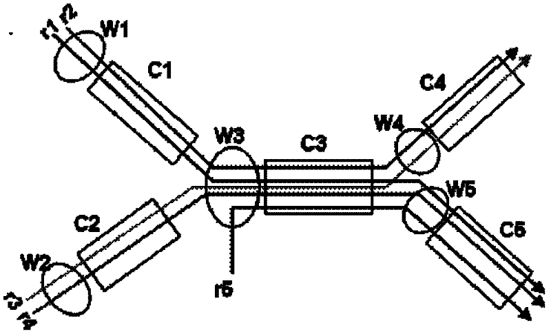
[0091] The following uses a partial topology structure of an actual UDP network as an example to show the advantages of the network bottleneck detection method of the present invention. The network topology is as image 3 shown. There is no ring data flow in this network. The network nodes are represented by independent ellipses according to the different output ports, and the links are represented by rectangles. The capacity of network nodes is marked as W, and the capacity of links is marked as C. The line represents the path through which the data flow passes. In this embodiment, there are 5 paths, and the initial input rate of each path is recorded as r j .

[0092] The detailed steps are as follows:

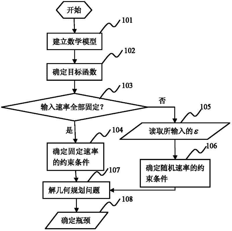
[0093] 101) Build a mathematical model

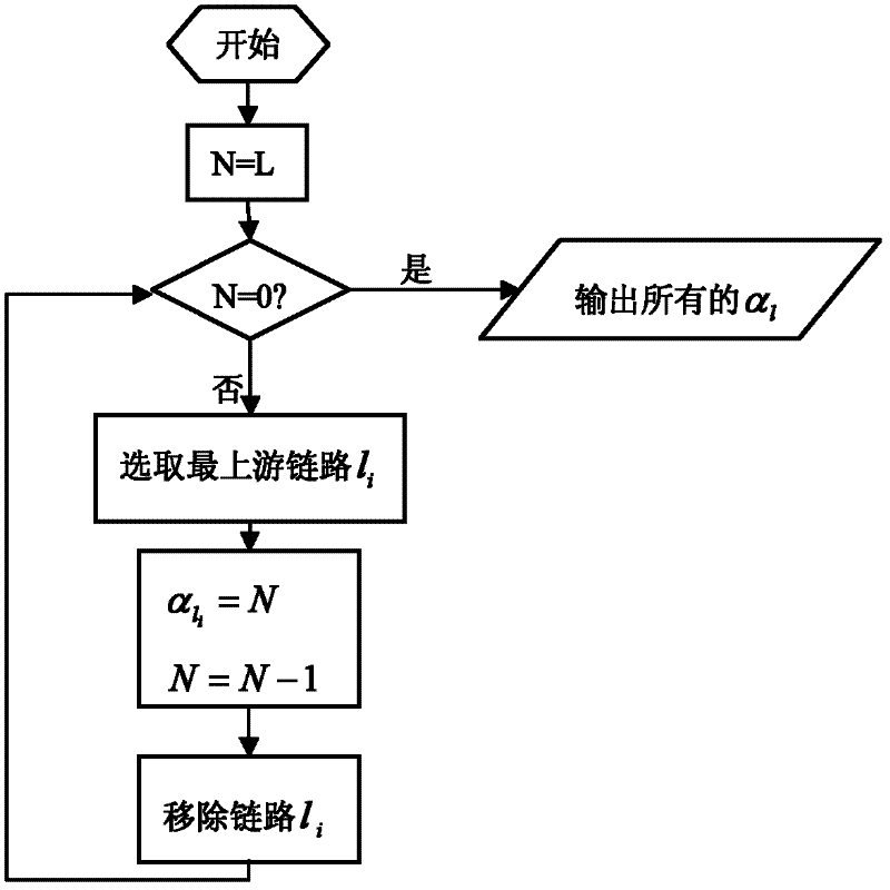
[0094] The network topology, links and routing information are obtained through network measurement technology, and the packet loss rate set of all links is recorded as L={l 1 , l 2 , l 3 , l 4 , l 5}, the link capacity set c...


PUM


Abstract

The present invention relates to the field of network technology, and discloses a network bottleneck detection method, including steps 101, establishing a mathematical model according to the network topology; 102, determining the objective function of the geometric programming problem according to the principle of network utility maximization; 103, judging all paths Whether all the input rates are fixed, if so, then execute steps 104, 107, 108 in sequence; otherwise, execute steps 105-108 in sequence; 104, determine the constraint condition of the fixed rate; 105, read the set insurance degree value ε; 106 107. Solve a geometric programming problem to obtain the packet loss rate of each link, wherein the geometric programming problem is composed of the objective function and a fixed-rate or random-rate constraint ; 108. Determine the network bottleneck according to the calculated packet loss rate of each link. The invention can improve the accuracy of network bottleneck detection, reduce network load, and improve the flexibility of network management.

Description

technical field [0001] The invention relates to the field of network technology, in particular to a network bottleneck detection method. Background technique [0002] By detecting network bottlenecks and analyzing the results, you can clearly understand the operation status of each component in the network, and at the same time reflect the operation status of abnormal components to users, and provide users with basis and reasonable suggestions in improving network performance and network service quality . Therefore, relevant analysis and research on network bottlenecks play an increasingly important role in the exploration of network performance management. Research and innovation of network bottleneck analysis algorithms play a decisive role in improving the overall performance of the network. Among many performance characteristics, bandwidth, delay, and packet loss rate are the three most commonly used indicators in network performance management, and they are also the th...

Claims


Application Information

Patent Timeline
Patent Type & Authority Applications(China)
IPC IPC(8): H04L12/26H04L1/00
Inventor 孟洛明邱雪松李娟熊翱王智立乔焰詹志强
Owner BEIJING UNIV OF POSTS & TELECOMM
Learn More