
Intelligent electricity grid

A smart grid and intelligent distribution technology, applied in the direction of electrical components, circuit devices, optical fiber transmission, etc., can solve the problems of increased construction costs, high application costs, and fragile glass optical fibers, and achieve vibration-resistant construction costs, convenient maintenance, and The effect of low connection cost

Active Publication Date: 2013-11-06
CENTURY OPTICOMM CO LTD
View PDF2 Cites 0 Cited by
  • Summary
  • Abstract
  • Description
  • Claims
  • Application Information

AI Technical Summary

Problems solved by technology

However, these two methods need to be built through different network architectures, so they do not meet the needs of smart composite grids. Integrating signal transmission and power transmission is the future development direction
[0004] There are also composite cables that integrate glass optical fibers and cables in the prior art. For example, two Chinese utility model patents with application numbers 201020135132.2 and 200920271986.0 each disclose a multi-core optical cable that integrates glass optical fibers and traditional power transmission cables to achieve simultaneous transmission. The purpose of power and communication signals, but there are still the following defects: First, the core diameter of the glass optical fiber is usually only a few to tens of microns, which encounters great difficulties in laying and installing the terminal of the smart grid-home smart grid, The construction cost is greatly increased; the second is that the glass optical fiber is fragile, which causes great difficulties in later maintenance. The above-mentioned combination of glass optical fiber and traditional cable is intelligently applied in long-distance transmission, and for the last part from the backbone network to the terminal, the application cost is relatively high. Large, unable to practice popularization

Method used


Image

  • Intelligent electricity grid
  • Intelligent electricity grid
  • Intelligent electricity grid

Examples


Embodiment 1

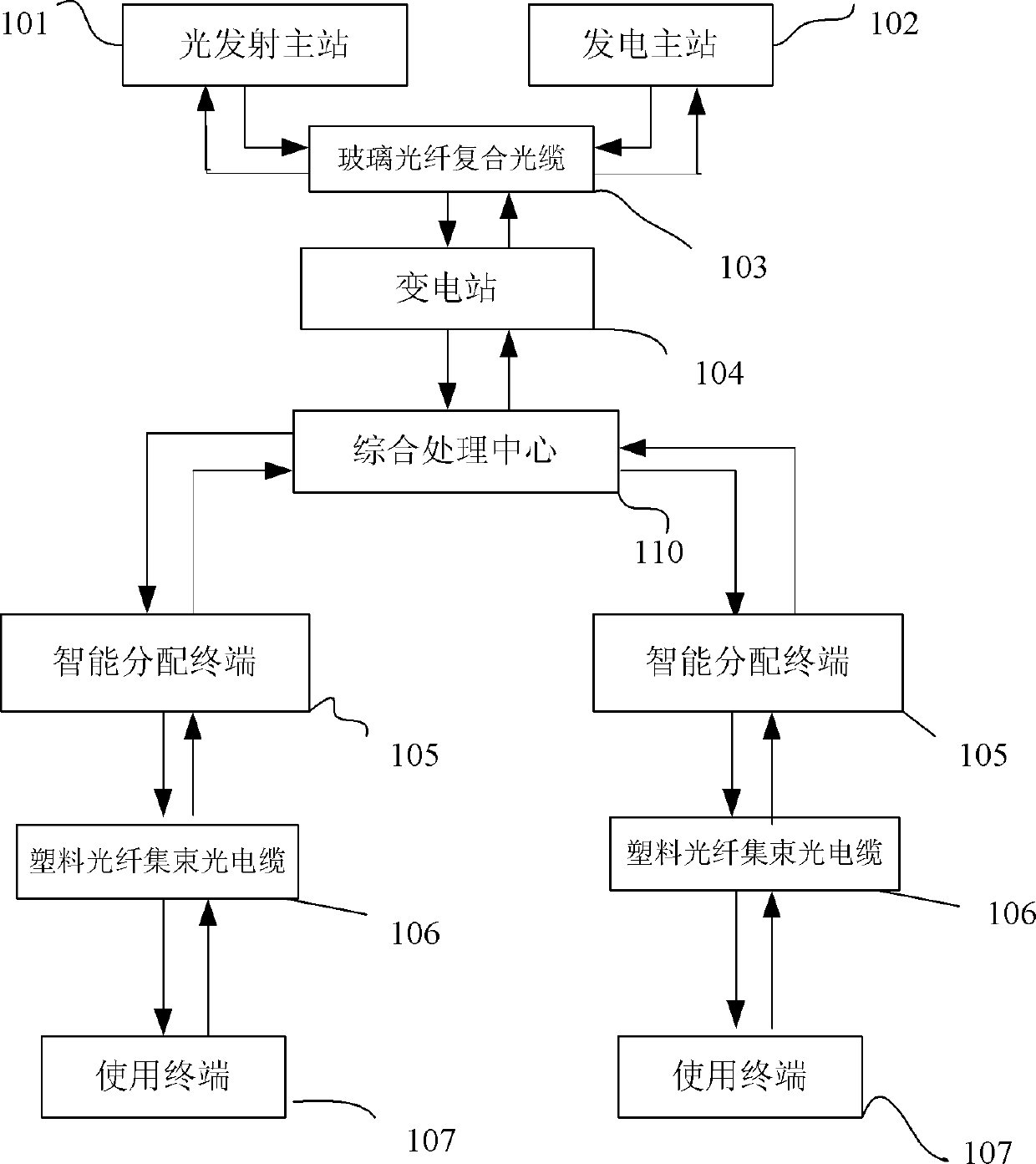
[0036] In the overall framework of this system, see Figure 4 , The power output from the power plant is transmitted to the substation through a composite optical cable formed by glass optical fibers and transmission cables. The transmission cables are responsible for transmitting power, while glass optical fibers are responsible for transmitting relevant information.

[0037] After entering the substation, the electricity is distributed and enters the comprehensive information processing unit 110 . In the integrated information processing center 110, the information transmitted by the optical fiber is processed, the power distribution and usage are optimized, and the information collected from the end users of the smart grid is stored and processed.

[0038] At the same time, the comprehensive information processing center 110 is connected to the Internet through an optical fiber to process information such as voice, image, and video. The integrated information processing ce...


PUM


Abstract

The invention provides an intelligent electricity grid, which comprises an optical-signal transmitting master station, a power-generation master station, a transformer station, a comprehensive treatment center, intelligent distribution terminals and use terminals, wherein optical signals transmitted by the optical-signal transmitting master station and electric energy of the power-generation master station are simultaneously transmitted to the transformer station through composite optical cables formed by glass optical fibers and cables, and are transmitted to the comprehensive treatment center after electric power distribution through the transformer station; and the electric energy transmitted through the composite optical cable is optimized in the comprehensive treatment center, the optical signals carried by the glass optical fibers are accessed to the Internet to carry out optical signal processing, and then the electric energy and the processed optical signals are transmitted to the intelligent distribution terminals through the composite optical cables formed by glass optical fibers and cables, and are simultaneously transmitted to the corresponding use terminals by the intelligent distribution terminals through plastic optical-fiber bunched optical cables integrated by plastic optical fibers and cables. The intelligent electricity grid provided by the invention has the advantages of low cost, high efficiency, and simpleness and easiness in maintenance.

Description

technical field [0001] The invention relates to a power and communication signal transmission network architecture, in particular to a new smart grid capable of simultaneously transmitting communication signals and electric energy. Background technique [0002] Smart grid refers to the intelligence of the power grid. It highly integrates and integrates many advanced technologies such as communication technology, computer technology, sensor measurement technology, and control technology with the original power grid facilities to form a new type of power grid, which represents the development trend of the future power grid. . [0003] Traditional communication networks and power transmission networks are often separated. For example, high-voltage lines are used as power transmission networks, while optical fibers are used for long-distance signal transmission, and twisted-pair wires are used for short distances. However, these two methods need to be built through different ne...

Claims


Application Information

Patent Timeline
Patent Type & Authority Patents(China)
IPC IPC(8): H02J13/00H04B10/25
Inventor 郭燕平刘竑凯
Owner CENTURY OPTICOMM CO LTD
Learn More