
Displacement Measuring Device

A technology of displacement measurement and measuring rod, applied in the direction of micrometer, etc., can solve the problems of deviation of measured value, difficult rotation of measuring rod, increase of friction force, etc.

Inactive Publication Date: 2011-11-30
MITUTOYO CORP
View PDF5 Cites 1 Cited by
  • Summary
  • Abstract
  • Description
  • Claims
  • Application Information

AI Technical Summary

Problems solved by technology

In this way, the torsional force applied to the operation sleeve and the force in the radial direction are directly transmitted to the measuring rod through the micrometer sleeve, so that the frictional force increases on the threaded part (external thread part) of the measuring rod, making it difficult for the measuring rod to to rotate
Therefore, the measurement force varies, and as a result, the measured value varies

Method used


Image

  • Displacement Measuring Device
  • Displacement Measuring Device
  • Displacement Measuring Device

Examples


Embodiment Construction

[0020] Hereinafter, embodiments of the present invention will be described based on the drawings. In this embodiment, an example of a digital micrometer will be described as a displacement measuring device.

[0021] Structure of digital micrometer

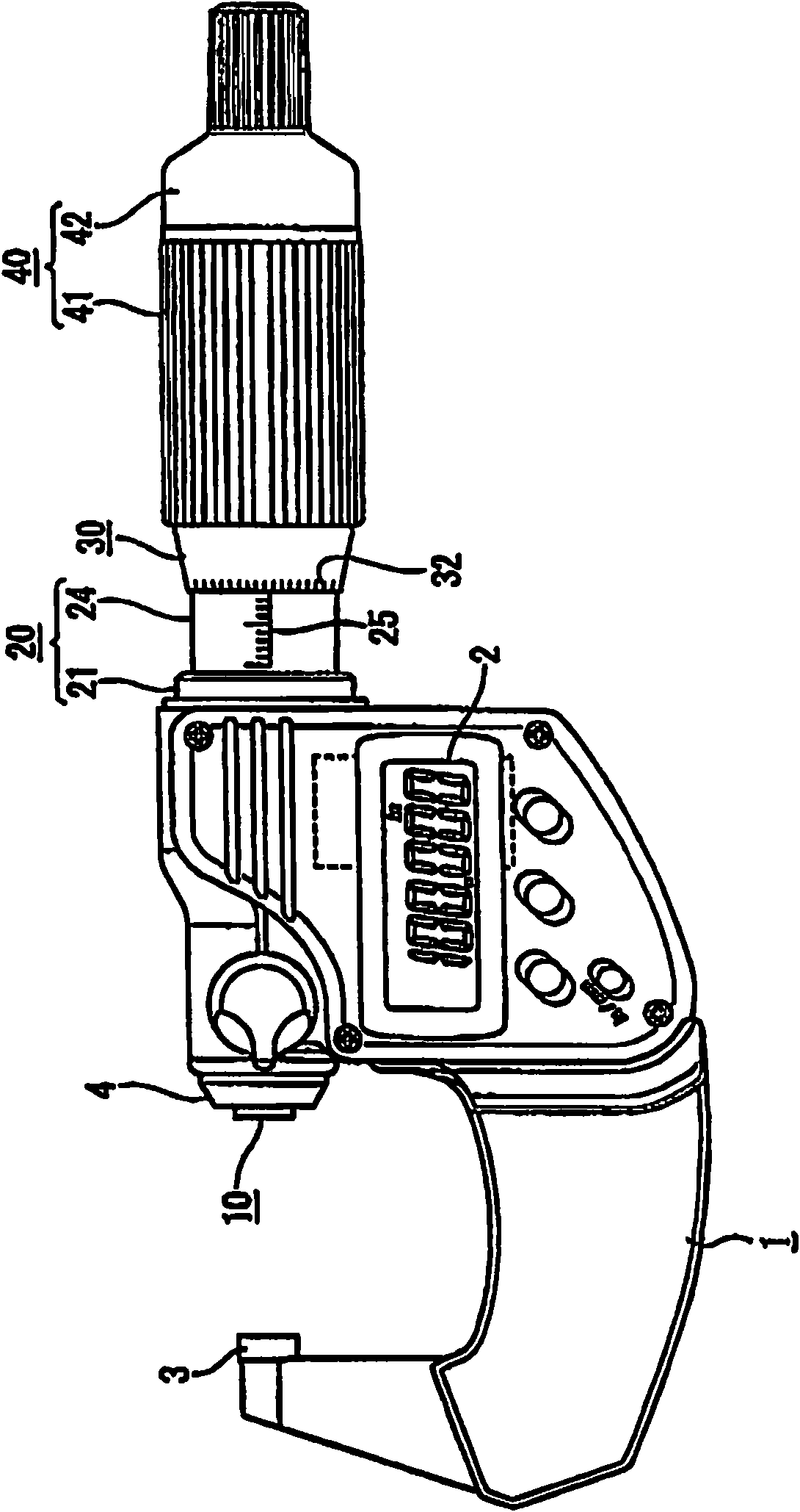
[0022] Such as figure 1 As shown, the digital micrometer has a substantially U-shaped main body 1, a measuring rod 10 slidably installed on the main body 1, and an encoder (not shown) for detecting the displacement of the measuring rod 10 inside the main body 1. . A digital display 2 for displaying the displacement (measured value) of the measuring rod 10 detected by the encoder.

[0023] An anvil 3 is fixed at one end of the main body 1 , and a bearing cylinder 4 for supporting the measuring rod 10 in a manner to support the measuring rod 10 to slide freely is provided at the other end.

[0024] The inner end side of the measuring rod 10 passes through the bearing cylinder 4 and is supported by the bearing cylinder 4 , and th...


PUM


Abstract

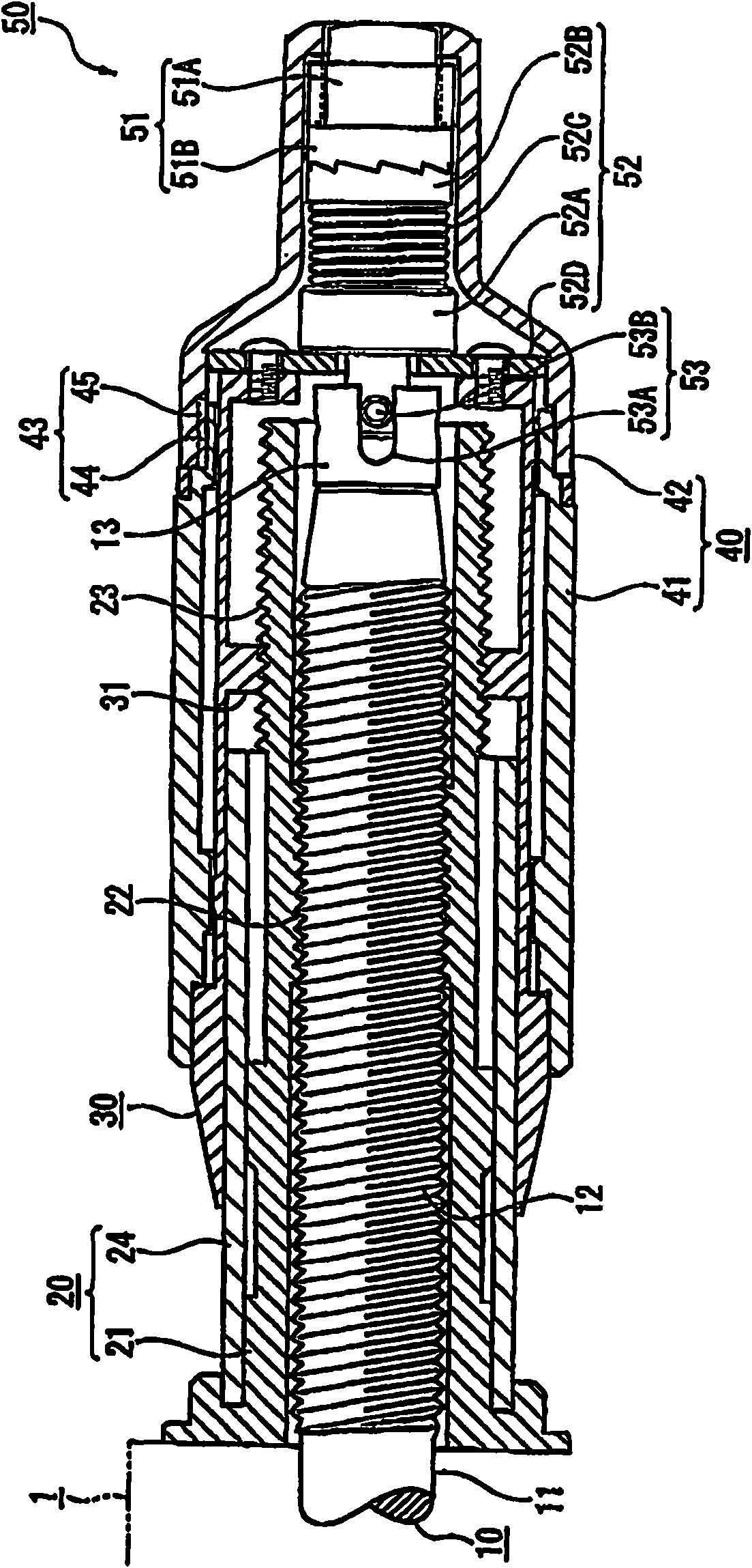
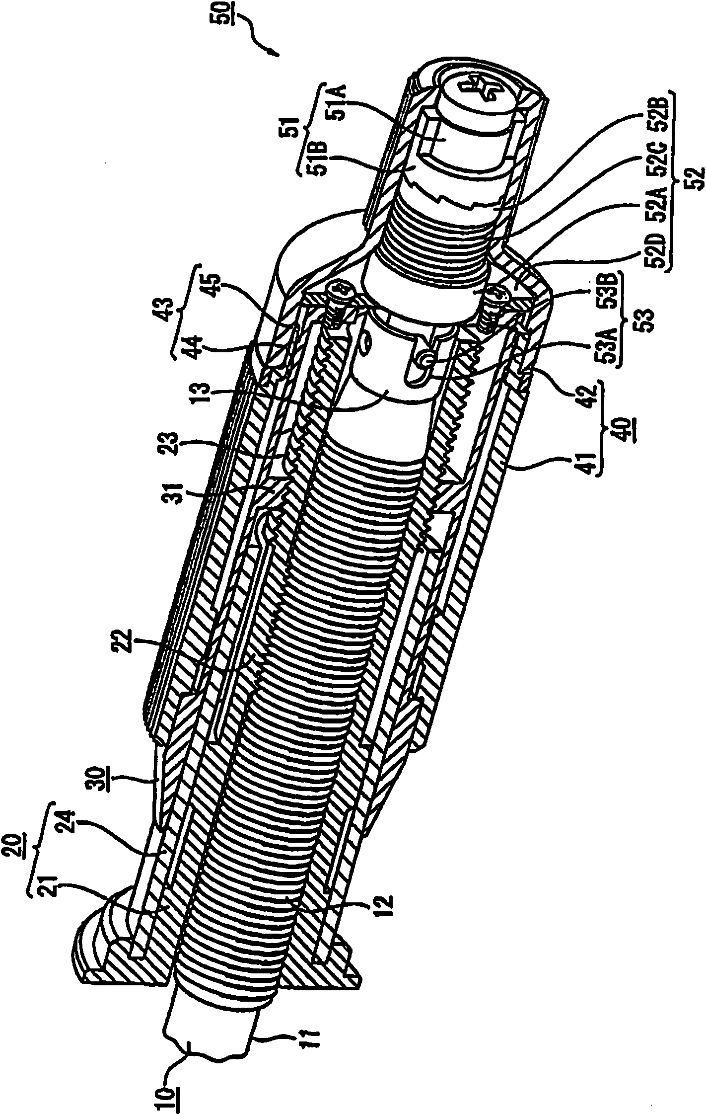
The invention provides a displacement measuring device. The displacement measuring device has a measuring rod (10) threadedly engaged with a fixed sleeve (20), a micrometer sleeve (30), an operating sleeve (40) and a constant pressure mechanism (50). The constant pressure mechanism includes: a rotary driving element (51), which rotates integrally with the operating sleeve; a rotating driven element (52), which is combined with the micrometer sleeve, and can rotate relative to the rotary driving element And it is connected to this rotation drive element so that it cannot rotate when a predetermined|prescribed load is applied to a probe rod, and a rotation transmission mechanism (53) transmits the rotation from a rotation driven element to a probe rod. An external thread portion (23) with the same pitch as the external thread portion (12) of the measuring rod is formed on the outer peripheral surface of the fixed sleeve, and an external thread portion (23) with the same pitch as the fixed sleeve is formed on the inner peripheral surface of the micrometer sleeve. An internally threaded portion (31) for threaded engagement.

Description

technical field [0001] The present invention relates to a displacement measuring device for measuring the size and the like of an object to be measured based on the displacement amount in the axial direction of a measuring rod. Background technique [0002] Among the micrometers that measure the size of the object to be measured based on the displacement amount in the axial direction of the measuring rod, there is disclosed a micrometer having a constant pressure mechanism capable of measuring the object to be measured with a substantially constant measuring force (refer to Document 1: Japanese Patent Application Laid-Open No. 2010-32365). [0003] The micrometer has the structure of the following components: a fixed sleeve, which is fixed on the main body; a measuring rod, which is threaded on the fixed sleeve and advances and retreats in the axial direction; a micrometer sleeve, which can be rotatably installed on the The outer circumference of the fixed sleeve and the ou...

Claims


Application Information

Patent Timeline
IPC IPC(8): G01B3/18
CPCG01B3/18
Inventor 辻胜三郎
Owner MITUTOYO CORP
Learn More