Special-shaped pipe for waste heat boiler and its processing method

A waste heat boiler and special-shaped tube technology, which is used in steam boilers, steam boiler accessories, steam boiler components, etc., can solve the problems of inconvenient welding, unstable quality, and uncertain shrinkage of pipe fittings, and achieves easy fixed welding, Improved convenience and heat dissipation

Inactive Publication Date: 2011-11-30
常熟市异型钢管有限公司
View PDF3 Cites 2 Cited by
  • Summary
  • Abstract
  • Description
  • Claims
  • Application Information

AI Technical Summary

Problems solved by technology

However, round pipes also have certain limitations. Special-shaped steel pipes are a general term for steel pipes with other cross-sectional shapes besides round pipes. Compared with round pipes, special-shaped pipes have greater bending and torsion resistance and are more adaptable to various There are two kinds of special conditions of use. Steel pipes are also divided into seamed steel pipes and seamless steel pipes. Seamed steel pipes are generally welded and cannot withstand high pressure. They cannot meet the requirements of waste heat boilers, and long-term use will increase inspection costs. Seamless steel pipes The steel pipe is a pipe with a hollow cross-section and no seams around it, and is widely used as a pipe for conveying fluids. The seamless special-shaped steel pipes in the prior art are not very convenient for welding, and the heat dissipation effect of common special-shaped pipes used in boilers It is not ideal. In the prior art, hot extrusion is used to produce seamless steel pipes, which has high cost and unstable quality, because the shrinkage rate inside the pipe fittings is uncertain, and it is difficult to guarantee the quality

Method used


Image

  • Special-shaped pipe for waste heat boiler and its processing method
  • Special-shaped pipe for waste heat boiler and its processing method

Examples


Embodiment Construction

[0016] The preferred embodiments of the present invention will be described in detail below in conjunction with the accompanying drawings, so that the advantages and features of the present invention can be more easily understood by those skilled in the art, so as to define the protection scope of the present invention more clearly.

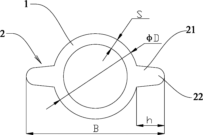
[0017] Such as figure 1 As shown, a special-shaped tube for a waste heat boiler of the present invention has an integrated structure, that is, seamless, which ensures its high-pressure resistance performance. It includes a cylindrical tube body 1 and two tubes along the radial direction of the tube body 1. The protruding part 2 is formed by extending outward. The protruding part 2 includes a connecting part 21 close to the tube body 1 and an outer end part 22 . The protruding part 2 is located on both sides of the tube body 1 symmetrically. The outer end surface of the outer end of the protruding part 2 is a convex arc surface, and the conne...


PUM


Abstract

The invention provides a special-shaped pipe for waste heat boilers. The special-shaped pipe has an integral structure, which includes a cylindrical pipe body and a protrusion extending radially outward from the pipe body. The protrusion includes a The connection part and the outer end part, the connection part of the surface of the connection part and the outer end part is rounded; the present invention also provides a method for processing the special-shaped pipe for waste heat boiler, including the following steps: (a) hot rolling; (b ) cold drawing, pickling and lubrication, and intermediate heat treatment; repeat the steps of cold drawing, pickling and lubrication and heat treatment until the desired finished special-shaped pipe is obtained; (c) heat-treat and temper the obtained finished special-shaped pipe; (d) Quenching and tempering; (e) Carry out flaw detection on the quenched and tempered special-shaped pipe to detect water pressure and internal environment. The invention adopts the cold drawing method to process the special-shaped pipe for the waste heat boiler, which has low cost and good stability, and the processed seamless special-shaped pipe is more resistant to high pressure, and the rounded structure of the protruding part of the special-shaped pipe improves the welding performance of the pipe fitting.

Description

technical field [0001] The invention relates to a pipe fitting, and more particularly to a special-shaped pipe for a waste heat boiler and a processing method thereof. Background technique [0002] Unlike conventional boilers, the waste heat boiler does not have a combustion process, but uses the heat generated in the industrial process. In essence, it is a gas-water / steam heat exchanger. The high-temperature flue gas from the combustion equipment passes through the flue It is sent to the inlet of the waste heat boiler, where the heat is utilized and then discharged into the atmosphere through the chimney. Boiler steel pipes can be divided into round pipes and special-shaped pipes according to the shape of the cross-sectional area. When the circumference is equal, the circle area is the largest. Relatively speaking, more fluids can be transported with round pipes; moreover, the ring When the cross-section is subjected to internal or external radial pressure, the force is...

Claims


Application Information

Patent Timeline
IPC IPC(8): F22B37/12B21C37/15
Inventor 张根明钱誉兰吴瑞忠
Owner 常熟市异型钢管有限公司
Why Eureka
Try Eureka