
Mold for automatically cutting water port in mold of common injection molding machine through cold pulling

A technology for injection molding machines and nozzles, applied in the field of plastic molds, can solve problems such as easy scratches on plastic parts, high prices, and difficulties in manual cutting, and achieve the effects of increasing average yield, reducing production costs, and improving indirect benefits

Inactive Publication Date: 2013-11-06
阳恒
View PDF7 Cites 0 Cited by
  • Summary
  • Abstract
  • Description
  • Claims
  • Application Information

AI Technical Summary

Problems solved by technology

At the same time, due to the particularity of the structure of a specific product, the glue can only be injected into the window hole in a small space or on the side wall of the product. The quality of the product often requires the glue to be injected in a large nozzle, and the injection mold of a large nozzle can only be done manually. Process the water cutout, and the remaining few injection molds with large nozzles can realize the automatic water cutout in the mold by complex row positions (also called sliders) and high costs such as fragile and expensive tools, let alone in the small space of the window. It is very difficult to manually cut the glue into the hole
Others such as needle-point thin nozzle, diving nozzle, banana nozzle (also called horn nozzle), half-banana nozzle (also known as half-horn nozzle, a new nozzle between the diving inlet and banana nozzle), pin-point hot water Although the nozzle, needle valve type hot water outlet, etc. can have the function of automatic water cut-off in the mold, they are either expensive or have molding defects, so they cannot replace the large nozzle.
At present, more than 60% of the molds are ordinary large nozzles, and the separation between the nozzle and the product can be realized only by manual post-processing and cutting of the nozzle: in this way, the labor cost is high, and the manual post-processing and cutting of the nozzle is very different, and the manual cutting of the nozzle requires a knife and plastic parts It is easy to scratch and not good, and people are also easy to be injured and fatigued
[0003] After searching the published literature, it is not found that the same technology as this technology and standardized cutting tools is used on plastic molds

Method used


Image

  • Mold for automatically cutting water port in mold of common injection molding machine through cold pulling
  • Mold for automatically cutting water port in mold of common injection molding machine through cold pulling
  • Mold for automatically cutting water port in mold of common injection molding machine through cold pulling

Examples


Embodiment 1

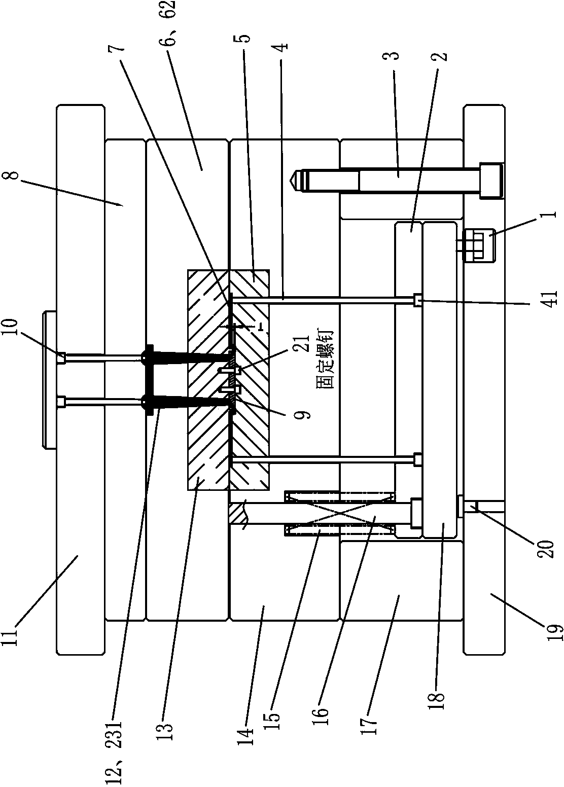
[0058] This mold (such as figure 1 As shown, mold clamping state) is made up of static mold base 11, static template 6, movable mold base 19, movable template 14, mold foot 17, injection molding machine top stick 22 etc.

[0059] Below the static mold base 11 is the nozzle plate 8, and below the nozzle plate 8 is the static formwork 6. There is a groove in the static formwork 6, and a static mold core 13 is embedded in the groove. 21 is fixed with nozzle cutter 9, and is fixed with nozzle pin 10 in static mold seat 11, and the upper end of nozzle pin 10 is nozzle pin cup head 101, and the lower end is inverted cone head 102, and nozzle plate hole 81 is arranged in nozzle plate 8 , the nozzle pin 10 is fixed in the static mold seat 11 through the nozzle pin cup head 101, the nozzle pin 10 can slide in the nozzle plate hole 81, the inverted cone head 102 is used to connect the large nozzle 12, and there is Two static formwork large nozzle main channels 61, there are two static ...

Embodiment 2

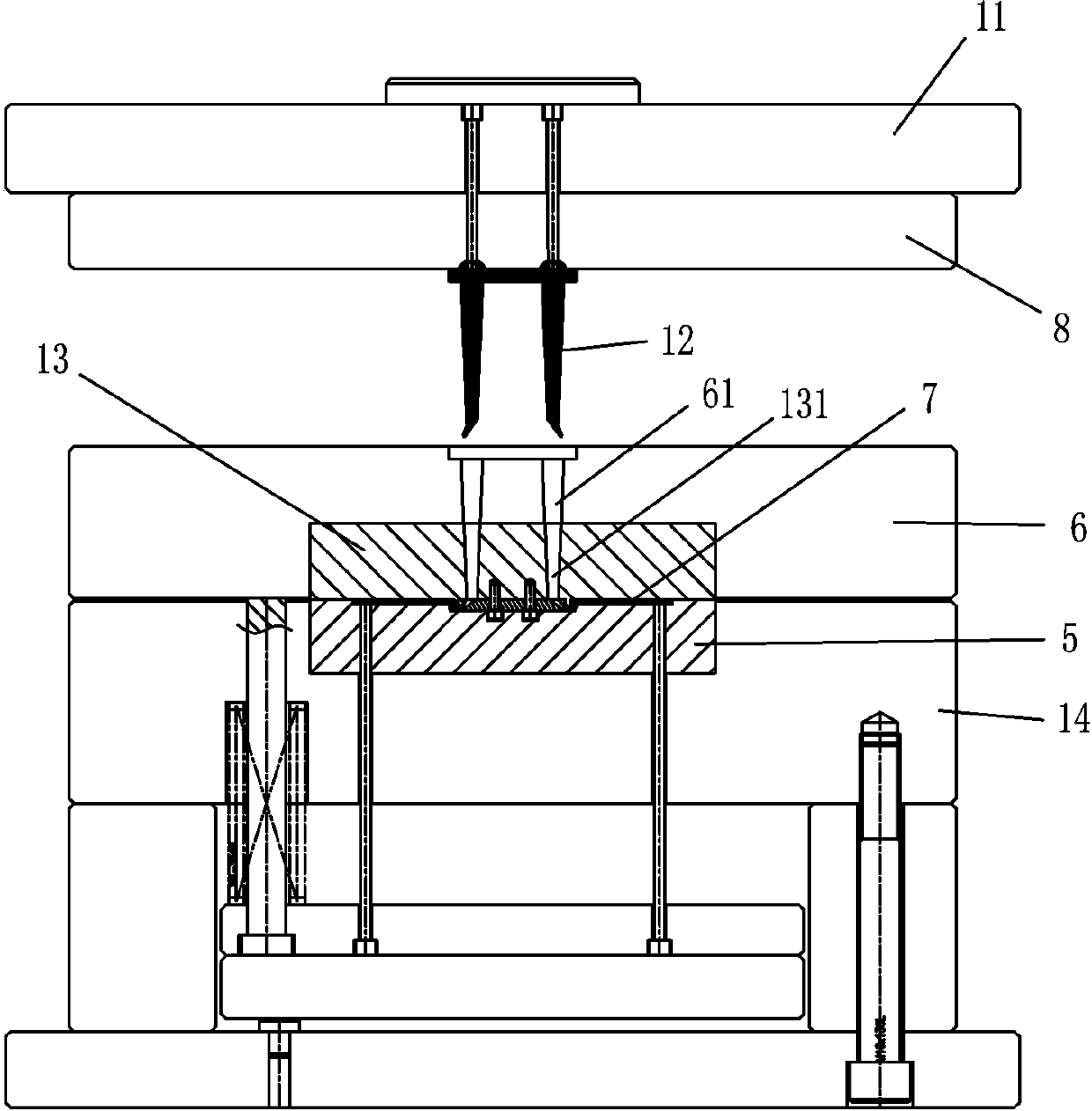
[0065] This mold (such as Figure 4 As shown, mold clamping state) is made up of static mold base 11, static template 6, movable mold base 19, movable template 14, mold foot 17, injection molding machine top stick 22 etc.

[0066] Below the static mold base 11 is the nozzle plate 8, and below the nozzle plate 8 is the static template 6. There is a groove in the static template 6, and a static mold core 13 is embedded in the groove. There are two static mold cores 13. Right-angled nozzle cutter mounting groove, nozzle cutter 9 is installed in this installation groove, and this nozzle cutter 9 is made up of right-angled cutter body 98 and boss cutter head 95, and there is underflow channel 91 in the boss cutter head 95, in static mold seat 11 A nozzle pin 10 is fixed inside, the upper end of the nozzle pin 10 is a nozzle pin cup head 101, the lower end is an inverted cone head 102, there is a nozzle plate hole 81 in the nozzle plate 8, and the nozzle pin 10 passes through the no...

Embodiment 3

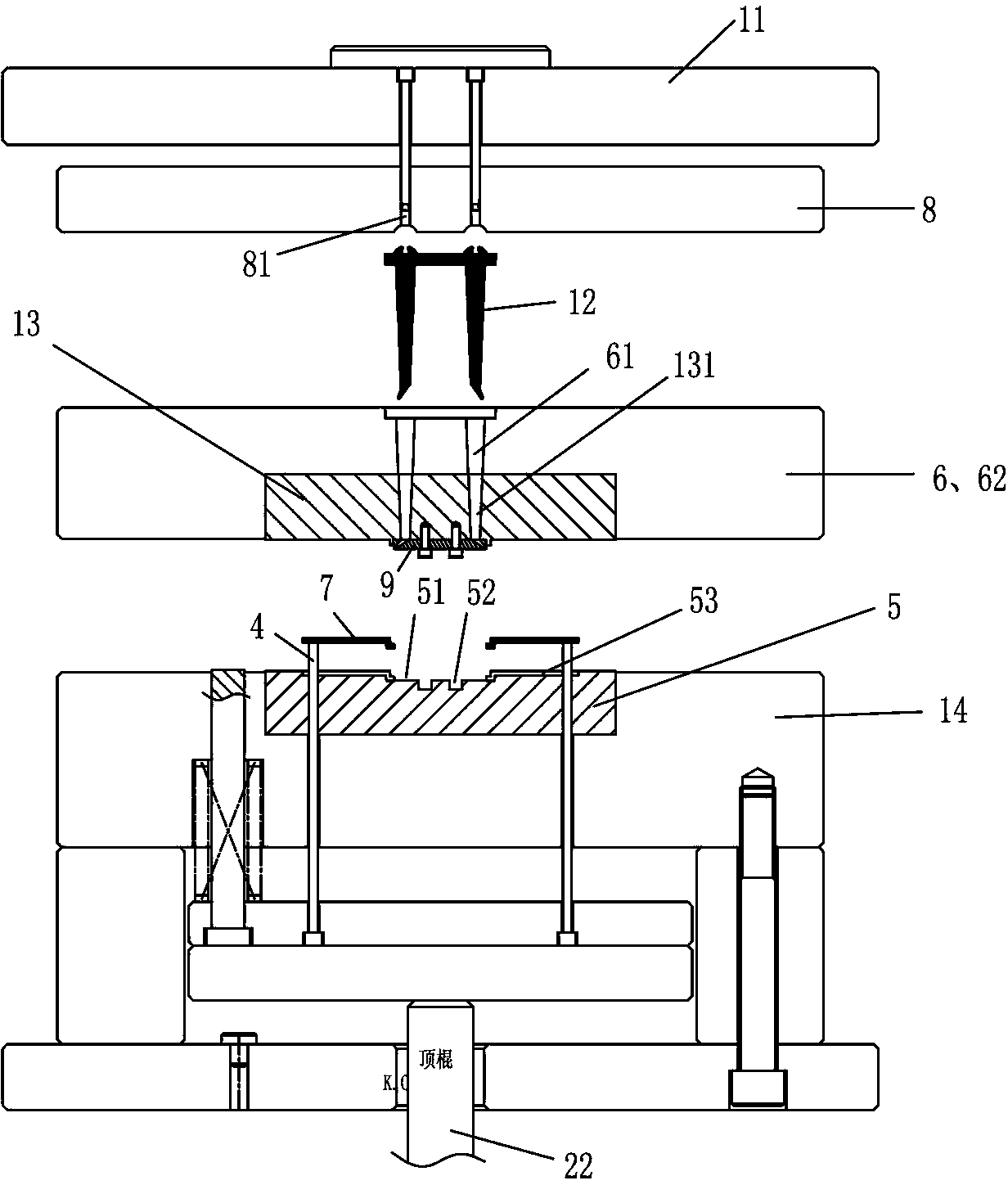
[0072] This mold (such as Figure 7 As shown, mold closing state) is composed of static mold base 11, static template 6, movable mold base 19, movable template 14, mold foot 17, injection molding machine top roller 22, etc.

[0073] Below the static mold base 11 is the nozzle plate 8, and below the nozzle plate 8 is the static template 6. There is a groove in the static template 6, and a static mold core 13 is embedded in the groove, and there is a place on the bottom surface of the static mold core 13. The nozzle cutter accommodating groove 51 of the right-angle nozzle cutter 9 is fixed with nozzle pin 10 in the static mold base 11, the nozzle pin 10 upper end is the nozzle pin cup head 101, and the lower end is an inverted cone head 102. There is a nozzle plate hole 81 inside, the nozzle pin 10 is fixed in the static mold base 11 through the nozzle pin cup head 101, the nozzle pin 10 can slide in the nozzle plate hole 81, and the inverted cone head 102 is used to connect the...


PUM


Abstract

The invention relates to a mold for automatically cutting a water port in a mold of the common injection molding machine through cold pulling. The mold comprises a fixed mold seat, a fixed mold plate, a movable mold seat, a movable mold plate, a mold foot and an injection molding machine top rod. The mold has four water port cutter structures, wherein 1, a water port cutter is arranged in a fixed mold core, and an underflow channel is formed in the water port cutter and is connected with a large water port main flow channel and a product cavity; 2, a water port cutter is arranged in a fixed mold core and comprises a cutter body and a cutter head, the cutter body is provided with a large water port main flow channel, and an underflow channel is formed on the cutter head and is connected with a product cavity; 3, a water port cutter is also arranged in a movable mold core, and an underflow channel is formed at the front end of a cutter body and is connected with a product cavity; and 4, a movable mold core is provided with a movable mold core boss and a large water port sub flow channel, the large water port sub flow channel is connected with a large water port main flow channel and a product cavity, and a glue inlet mode is a large water port bottom lapping glue inlet mode. The mold automatically cuts the water port in the mold in a mode of separating a product from a large water port sprue through cold pulling and cutting.

Description

technical field [0001] The invention relates to a plastic mold for an ordinary injection molding machine, and mainly refers to a mold for an ordinary injection molding machine with internal cold pulling and automatic water cutting. Background technique [0002] At present, the injection molding machines of most injection molding companies are traditional ordinary injection molding machines without mold clamping and ejection functions. This kind of ordinary injection molding machines accounts for more than 99% of the world's share. At the same time, due to the particularity of the structure of a specific product, the glue can only be injected into the window hole in a small space or on the side wall of the product. The quality of the product often requires the glue to be injected in a large nozzle, and the injection mold of a large nozzle can only be done manually. Process the water cutout, and the remaining few injection molds with large nozzles can realize the automatic wat...

Claims


Application Information

Patent Timeline
Patent Type & Authority Patents(China)
IPC IPC(8): B29C45/38B29C45/26
Inventor 阳恒
Owner 阳恒
Learn More