
Stator winding connection method for low-voltage high-power multipole multiphase permanent magnet synchronous motor

A permanent magnet synchronous motor and stator winding technology, which is applied to the shape/style/structure of synchronous machine components and winding conductors, and can solve the problems of large total cross-sectional area of ​​phase winding conductors, reduced motor performance, and low battery voltage. , to achieve the effect of reducing the cross-sectional area of ​​the coil conductor, reducing the cross-sectional area of ​​the conductor, and improving the performance of the motor

Inactive Publication Date: 2011-11-23
TIANJIN UNIV
View PDF3 Cites 17 Cited by
  • Summary
  • Abstract
  • Description
  • Claims
  • Application Information

AI Technical Summary

Problems solved by technology

In practice, for multi-phase multi-pole induction motors, the ideal conclusion still applies, however, for multi-phase multi-pole permanent magnet synchronous motors, the problem is exposed
The reason is that a large number of permanent magnets must be used on the multi-pole permanent magnet rotor. Relying on the residual magnetism of the permanent magnets after saturated magnetization, the motor provides the necessary medium for electromechanical energy conversion - the air gap permanent magnet magnetic field, forming the expected multiple in the motor. There are multiple pairs of permanent magnet poles between N and S phases, but the magnetic properties of commercial permanent magnets have a large dispersion.
When the inconsistency of permanent magnet magnetic properties is serious, it will cause the air gap permanent magnet flux under each magnetic pole of the permanent magnet rotor to be different, so that the permanent magnet induced electromotive force in each parallel branch of each phase winding is different, and in each parallel branch of each phase winding Circulation is generated between circuits, resulting in additional loss, resulting in a decrease in motor performance
Therefore, in order to avoid such adverse effects, usually, when designing multi-phase multi-pole permanent magnet synchronous motors, scientific and technological workers only design the stator windings of each phase as one parallel branch, and adjust the number of coils in each slot. The number of turns will cause a large change in the number of series turns of the phase winding, and at the same time, the total cross-sectional area of ​​the conductor of the phase winding is large
For limited stator slots, when the motor power is large, the battery voltage is low, and the total current of each phase is large, the adjustment of the number of series turns of the phase windings and the effective use of the slots will become two major problems, and it is not easy to design A permanent magnet synchronous motor with various performances

Method used


Image

  • Stator winding connection method for low-voltage high-power multipole multiphase permanent magnet synchronous motor
  • Stator winding connection method for low-voltage high-power multipole multiphase permanent magnet synchronous motor
  • Stator winding connection method for low-voltage high-power multipole multiphase permanent magnet synchronous motor

Examples


specific example

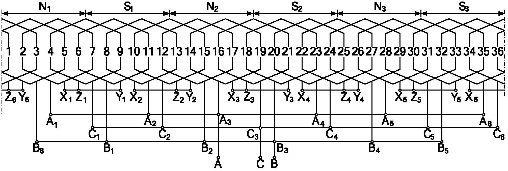
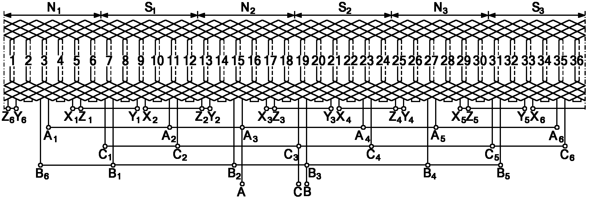
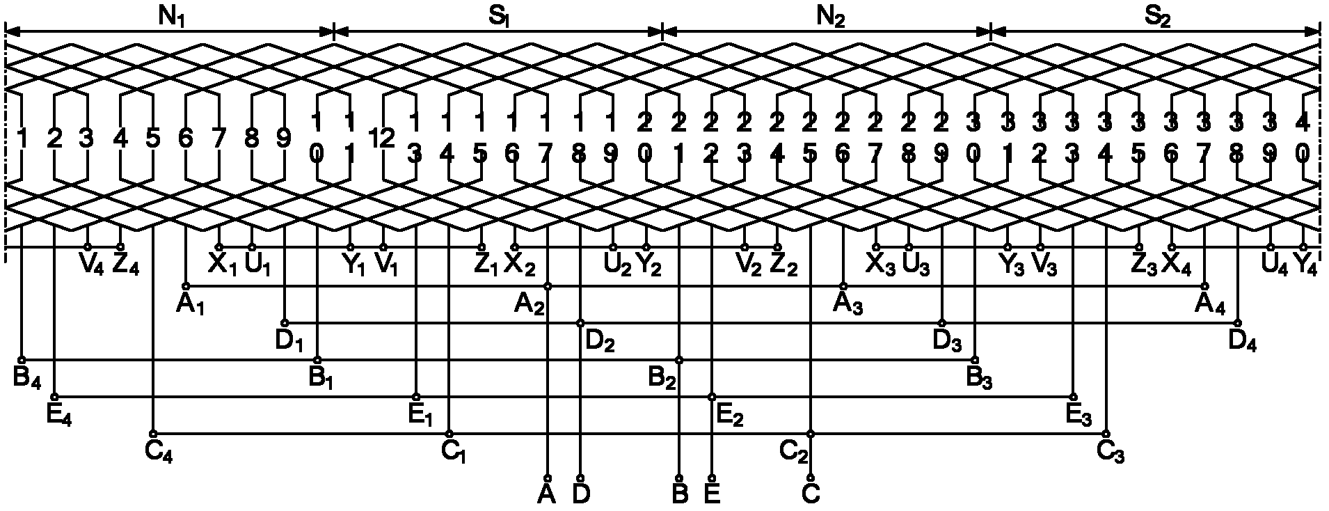
[0018] as attached figure 1 As shown, the number of motor phases m=3, the number of poles 2p=6, the number of stator slots Z=36, the windings are divided into phases according to π / 3 electrical angle, and are connected into 6 star-connected groups in parallel according to the present invention, and each star contact Unconnected AC motor stator single layer winding. In the figure, N 1 , S 1 , N 2 , S 2 , N 3 , S 3 Represents the 6 magnetic poles of the motor rotor, and the numbers 1, 2, L, 35, 36 represent the serial numbers of the 36 slots of the motor. There are 18 coils placed in the stator, and the number of turns of the coils is N. c . A 1 X at the end 1 Coil A 1 x 1The two coil sides of A are respectively embedded in slot 2 and slot 7, and coil A 1 x 1 This coil itself constitutes the first coil group of phase A; the end is A 2 X 2 Coil A 2 x 2 The two coil sides of A are respectively embedded in slot 13 and slot 8, coil A 2 x 2 This coil itself constit...


PUM


Abstract

The invention discloses a stator winding connection method for a low-voltage high-power multipole multiphase permanent magnet synchronous motor. In the invention, for an AC (alternating current) motor of which the phase number is m, the pole number is 2p, the stator slot number is Z, phase splitting is carried out according to a pi / m electrical angle, and the maximum number of coil assemblies which can be connected in parallel in each phase is amax, in the method disclosed by the invention, each coil assembly which can be connected in parallel in each phase of the stator winding is taken as abranch, m branches of the adjacent m phases in space can be connected to form a m-phase symmetrical starlike connection group according to a rule of electromotive force phase mutual difference 2pi / m electrical angle, and then the head ends of each branch belonging to the same phase in the obtained amax starlike connection groups are connected in parallel while the amax star contacts are not connected; thus, the stator winding can be formed by connecting the amax m-phase symmetrical starlike connection groups in parallel, the total number of series turns of each coil assembly is the number of series turns of each phase winding, and the stator winding is an m-phase symmetrical winding. The method is convenient to adjust the series turns of each phase of the stator winding and the slot utilization and can reduce the circulation probably generated by the paralleled windings.

Description

technical field [0001] The invention relates to a stator winding connection method of a synchronous motor. In particular, it relates to a stator winding connection method for a low-voltage high-power multi-pole multi-phase permanent magnet synchronous motor that can realize the stator winding of a multi-phase multi-pole AC motor and can be flexibly arranged. Background technique [0002] At present, a considerable part of the driving motors used in many pure electric vehicles and hybrid vehicles are two kinds of AC motors, induction motors or permanent magnet synchronous motors. A considerable number of technical solutions for the power supply of the motor are to use batteries, and the power of the motor varies from several kilowatts to tens of kilowatts. In this workplace, the AC motor has to face the reality of low voltage and high current. Low voltage means that the number of series turns of each phase winding is small, and high current means that the total cross-section...

Claims


Application Information

Patent Timeline
IPC IPC(8): H02K21/02H02K3/28
Inventor 陈益广
Owner TIANJIN UNIV
Learn More