Eureka AIR delivers breakthrough ideas for toughest innovation challenges, trusted by R&D personnel around the world.

Low-position light-emitting diode (LED) lighting device of tunnel

A technology of LED lighting and LED chips, which is applied to lighting devices, fixed lighting devices, components of lighting devices, etc. The effect of prolonging the life, solving the problem of glare, and sufficient brightness

Inactive Publication Date: 2011-11-23
ZHEJIANG AIKE TECH +1
View PDF0 Cites 2 Cited by
  • Summary
  • Abstract
  • Description
  • Claims
  • Application Information

AI Technical Summary

Problems solved by technology

[0002] In the existing tunnel lighting, using the lighting method of overhead light source, installation, use, maintenance, high cost and high risk, the above work can only be carried out after the traffic is interrupted. Tunnel lighting is a worldwide problem, especially in underground tunnels , the installation and maintenance are more difficult and dangerous. The lamps and lanterns work in the harsh environment of humidity, vibration and wind pressure, and the damage rate is relatively high. It will be more troublesome to replace or repair each time. The reflector will be irradiated by direct light from the side, and the driver's vision will be very uncomfortable, which will easily cause traffic accidents

Method used


Image

  • Low-position light-emitting diode (LED) lighting device of tunnel
  • Low-position light-emitting diode (LED) lighting device of tunnel
  • Low-position light-emitting diode (LED) lighting device of tunnel

Examples


Embodiment

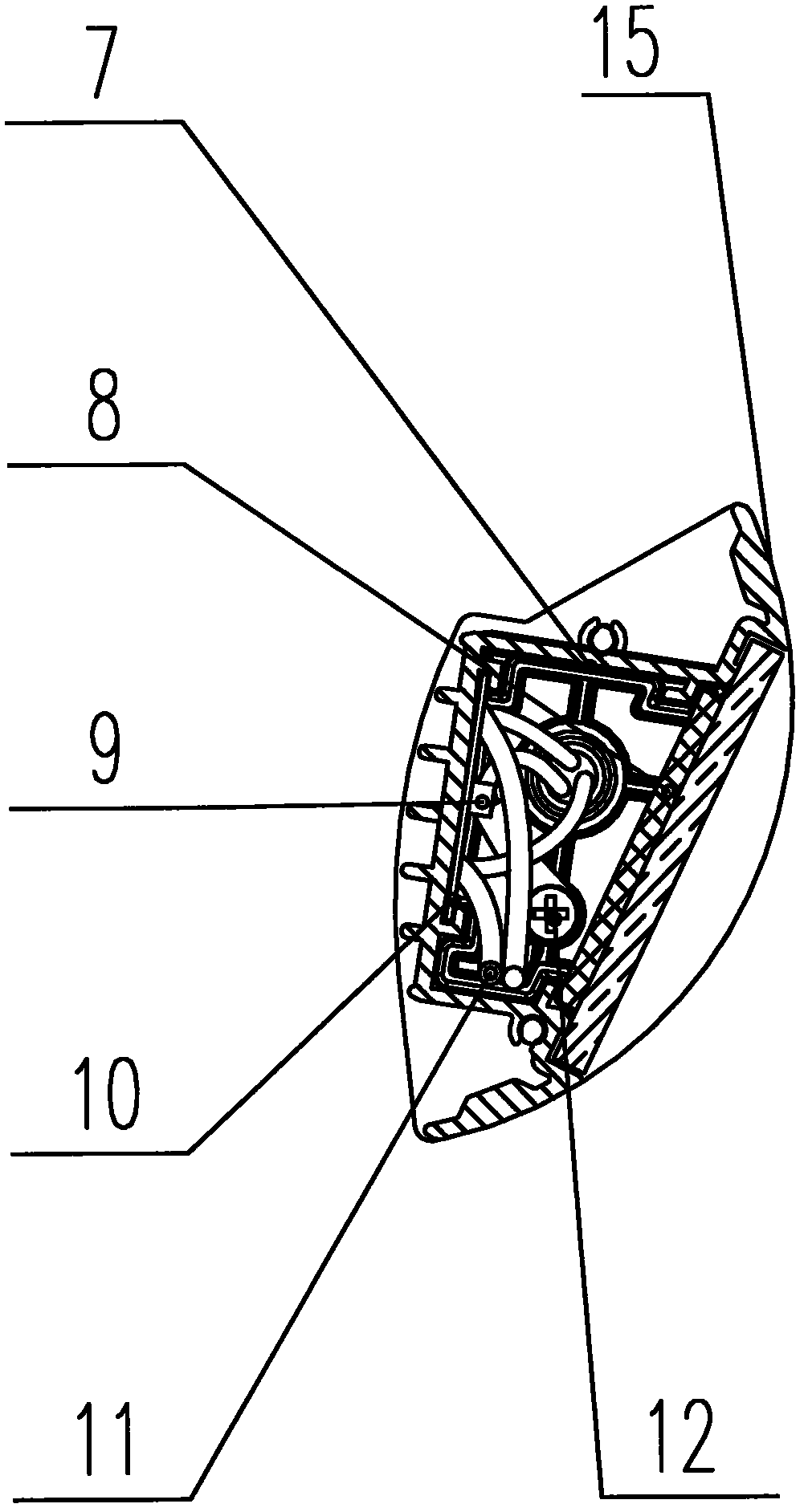
[0027] see figure 1 , the tunnel low-level LED lighting device, including a lamp body profile 3, a glass plate 4 and a light-diffusing light-transmitting plate 41 arranged in the lamp body profile 3, and end caps 2 and 5 encapsulated on both sides of the lamp body profile 3, Insert the female plug 1 into the 2 holes of the end cover, insert the male plug 6 into the 5 holes of the end cover, the buckle cover 14 that matches the female plug 1, and the buckle cover 15 that matches the male plug 6;

[0028] Pins are set in the male plug 6, and jacks are set in the female plug 1, and the pins are correspondingly inserted into the jacks to achieve the purpose of connecting the male plug 6 and the female plug 1; One of the plug 6 and the female plug 1 is connected to the AC L and N of the commercial power, and can also be connected to a DC power supply.

[0029] The buckle cover 14 tightly connects the female plug 1, the end cover 2 and the lamp body profile 3 through the positionin...


PUM


Abstract

The invention discloses a low-position light-emitting diode (LED) lighting device of a tunnel. The device comprises a lamp body sectional material, a glass plate, a light-diffusion type light transmission plate, two end covers, a male plug, a female plug and two buckling covers, wherein the glass plate and the light-diffusion type light transmission plate are positioned in the lamp body sectional material; the two end covers are packaged on two sides of the lamp body sectional material; the male plug and the female plug are connected with the two end covers respectively; the two buckling covers are positioned on the outermost side and connected with two ends of the lamp body sectional material respectively; an LED chip, a reflecting plate, a diffusion plate and a lamp bar plate are arranged in one buckling cover; the lamp bar plate is a printed circuit board (PCB) and arranged on the side part of the LED chip; and the diffusion plate is arranged on the other side, opposite to the lamp bar plate, in the buckling cover. The LED chip is modularized to facilitate adjustment of brightness and an irradiation distance; and the glass plate and the light-diffusion type light transmission plate realize secondary light-changing performance and make a light source diffused. The low-position LED lighting device of the tunnel has the advantages that: the structure is smart; light emitting brightness is high by using the technologies of light emitting of an LED chip module and secondary light changing; glare is avoided; and visual comfortability is improved.

Description

technical field [0001] The invention relates to the field of LED lighting, in particular to a tunnel low-position LED lighting device. Background technique [0002] In the existing tunnel lighting, using the lighting method of overhead light source, installation, use, maintenance, high cost and high risk, the above work can only be carried out after the traffic is interrupted. Tunnel lighting is a worldwide problem, especially in underground tunnels , the installation and maintenance are more difficult and dangerous. The lamps and lanterns work in the harsh environment of humidity, vibration and wind pressure, and the damage rate is relatively high. It will be more troublesome to replace or repair each time. The reflector will be irradiated by side direct light, which will make the driver's vision very uncomfortable and easily cause traffic accidents. Contents of the invention [0003] In order to overcome the above-mentioned defects in the prior art, the present inventio...

Claims


Application Information

Patent Timeline
Patent Type & Authority Applications(China)
IPC IPC(8): F21S8/00F21V23/06F21V13/04F21W131/101F21Y101/02
Inventor 翁延鸣
Owner ZHEJIANG AIKE TECH
Why Eureka
Eureka Blog
Learn More