Demoulding device for thin-wall deep-drawing part process
A stripper and deep drawing technology, used in manufacturing tools, metal processing equipment, peeling devices, etc., can solve the problems of instability and wrinkling of cans, increase the difficulty of demolding, etc., to reduce the difficulty of demolding and prevent damage. The effect of pressure instability
- Summary
- Abstract
- Description
- Claims
- Application Information
AI Technical Summary
Problems solved by technology
Method used
Image
Examples
Embodiment 1
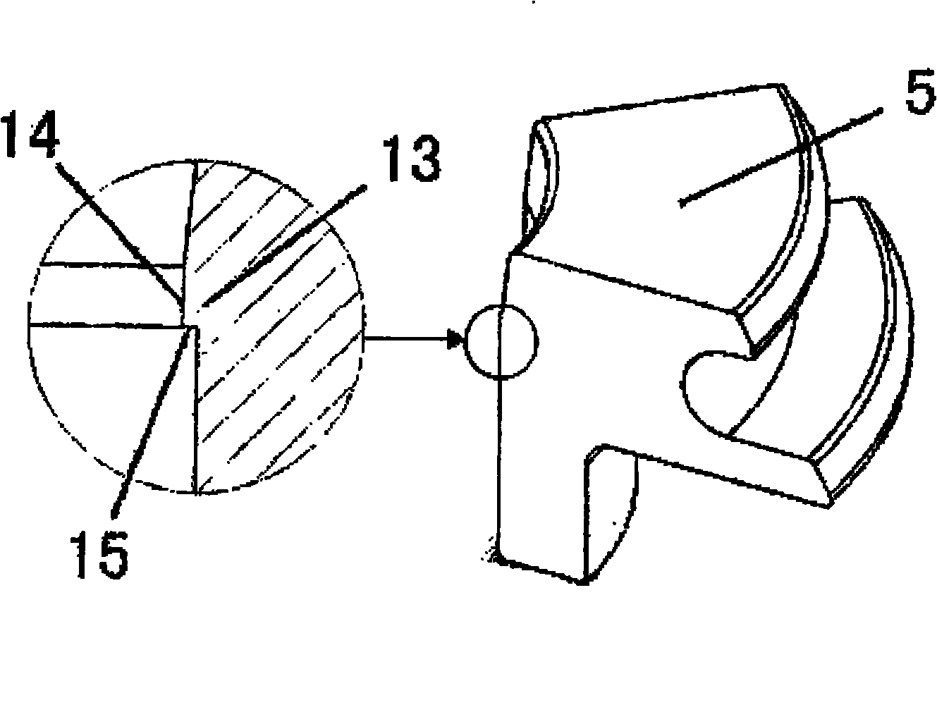
[0025] The installation method of the demoulding device used in this thin-walled deep drawing part process is as follows: image 3 The 8 discharge blocks shown are put together into a circle, and are fixed with a rubber ring 6 in the U-shaped groove of the flange to form a Figure 5 The unloading ring 2 shown. Flange inclined-plane 8 of unloading ring 2 and Figure 6 The inclined surface 9 of the tapered hole seat 1 shown is in contact with each other, and these two surfaces need to have relatively low roughness and low coefficient of friction, so that they can easily slide against each other. When the unloading block is processed, the diameter of the inner flange mouth is required to be about 0.05mm smaller than the outer diameter of the workpiece after thinning and deep drawing. Such as Figure 7 As shown in the material guide cylinder 3, the upper surface 11 of the material guide cylinder 3 is in contact with the surface 12 of the unloading ring 2, and both are also requ...
Embodiment 2
[0027] The movement mode of the demoulding device used in the thin-walled deep-drawing process is specifically: after the thinning and deep-drawing is completed, the punch drives the pot-shaped thin-walled workpiece to enter the unloading ring 2 from top to bottom. When the workpiece passes through the inner flange 14 ( image 3 As shown), because the diameter of the inner flange of the unloading ring 2 is smaller than the outer diameter of the workpiece, the unloading ring 2 is forced to expand, and the surface 8 of the outer flange of the unloading ring 2 slides downward along the slope 9 of the taper hole seat 1, and the surface 12 slides radially along the upper surface 11 of the material guide cylinder 3, pushing the material guide cylinder 3 to compress the spring 7 downward. When the workpiece completely passes through the inner flange 14 of the unloading ring 2, the radial expansion force on the unloading ring 2 is removed, the rubber ring 6 shrinks, and the spring 7 e...
PUM
 Abstract
Description
Claims
Application Information
 - R&D
- Intellectual Property
- Life Sciences
- Materials
- Tech Scout
- Unparalleled Data Quality
- Higher Quality Content
- 60% Fewer Hallucinations
Browse by: Latest US Patents, China's latest patents, Technical Efficacy Thesaurus, Application Domain, Technology Topic, Popular Technical Reports.
© 2025 PatSnap. All rights reserved.Legal|Privacy policy|Modern Slavery Act Transparency Statement|Sitemap|About US| Contact US: help@patsnap.com


