
Method for adjusting verticality of rolling mill

An adjustment method and verticality technology, applied in the direction of metal rolling, metal rolling, length measuring device, etc., can solve the problems of large cumulative error, inaccurate data, increase in manpower, material resources, and time, so as to reduce the impact and ensure Accuracy, effect of reducing export steps

Active Publication Date: 2011-11-16
TIANJIN XINBIN ENG TECH INSPECTION
View PDF6 Cites 11 Cited by
  • Summary
  • Abstract
  • Description
  • Claims
  • Application Information

AI Technical Summary

Problems solved by technology

This alignment method has the following disadvantages: 1. Not directly measuring the verticality may cause the measured data to be inaccurate
2. There are errors in each step, resulting in excessive cumulative errors
3. Causes an increase in manpower, material resources and time
4. In the adjustment of the verticality between the bottom plate of the rolling mill stand, the archway and the rolling line, the installation accuracy cannot be achieved

Method used


Image

  • Method for adjusting verticality of rolling mill
  • Method for adjusting verticality of rolling mill
  • Method for adjusting verticality of rolling mill

Examples


Embodiment 1

[0036] The verticality measurement between the rolling mill floor and the rolling line (such as Figure 15 ):

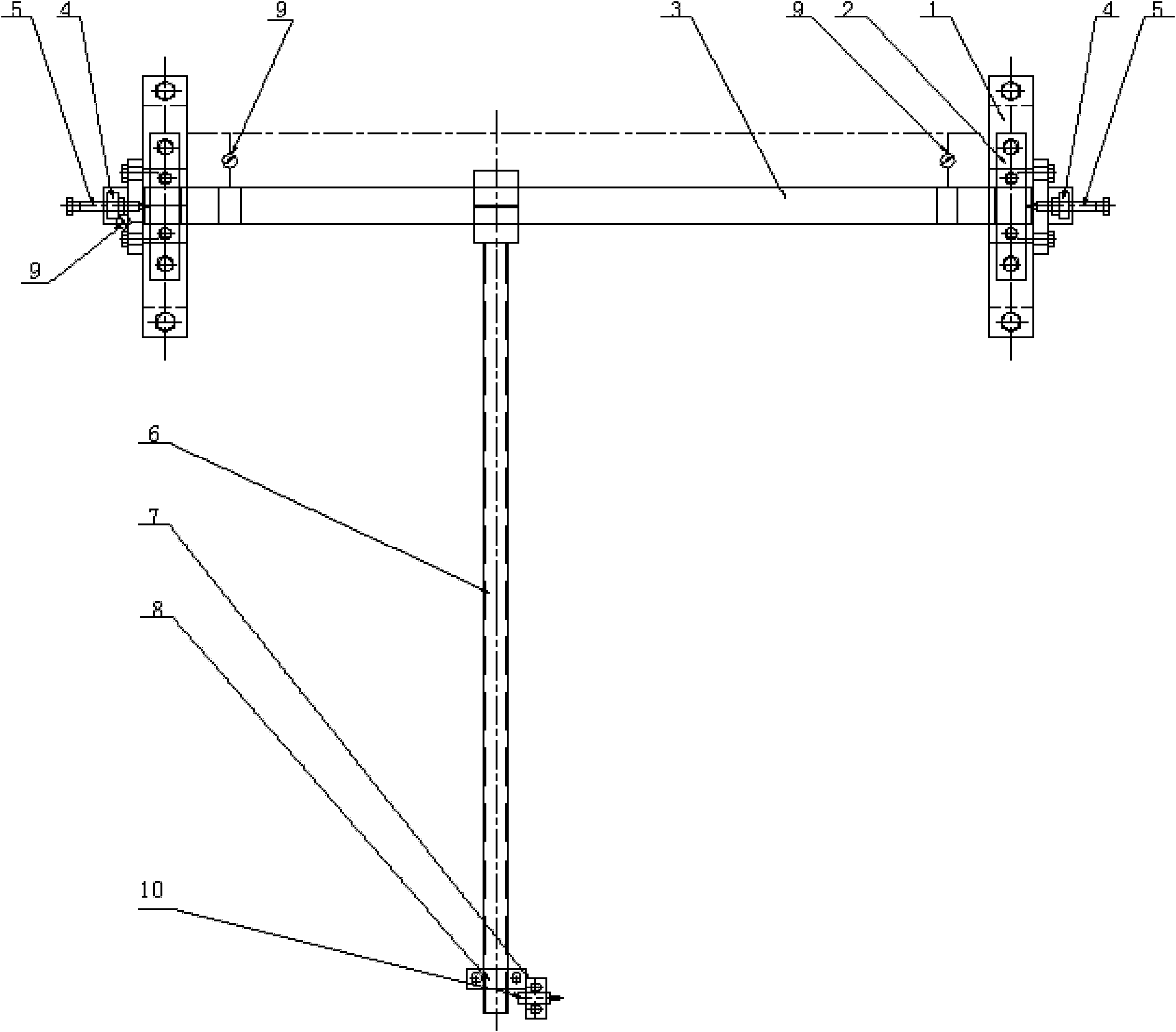
[0037] Fix the second base of the pendulum tool 12 on the bottom plate 13 of the rolling mill stand, fix the two dial gauges 9 on the bottom plate 13 of the rolling mill stand through the magnetic base, and the detection rod of the dial indicator 9 measures the radial surface of the shaft , rotate the rocker arm 6 of the pendulum tool and adjust the sliding bearing 2 at the first base so that the reading of the two dial indicator 9 remains basically unchanged, and then place the dial indicator 9 on the shaft end, and the detection rod of the dial indicator 9 measures the shaft end surface , detect the axial displacement of the shaft during the pendulum process, install a micrometer 10 in the fixture 8, listen to the sound with earphones, rotate the rocker arm 6 of the pendulum tool 12 to two predetermined positions on the piano line, and read the micrometer 10 and T...

Embodiment 2

[0039] Perpendicularity measurement between arch base window and rolling line (such as Figure 18 )

[0040] Utilize the jack 16 and the support 17 to fix the steel level ruler 14 on the vertical plane of the two archways 15 of the rolling mill stand, measure with a square level to keep the level ruler 14 level, and fix the first base of the pendulum tool 12 on the level ruler 14, and then measure the perpendicularity between the benchmark window of the rolling mill frame archway and the rolling line according to Example 1.


PUM


Abstract

The invention discloses a method for adjusting the verticality of a rolling mill in mounting accuracy, and the method the following steps of: (1) erecting a piano line at a rolling center line of the rolling mill; (2) fixing a base at one side of a swinging tool on the base plate of a rolling mill rack or mounting the base on a steel levelling rule according to measuring requirements; (3) fixing two dial gauges on the base plate of the rolling mill rack or the steel levelling rule by virtue of a magnetic gauge stand, rotating the rocker arm of the swinging tool, and adjusting a sliding bearing arranged at a base at the other side of the swinging tool to cause the indications of the two dial gauges to be constant; (4) placing a third dial gauge at one lateral shaft end of the swinging tool, detecting the axial displacement of a shaft in a swinging process; and (5) mounting an inner diameter micrometer in the fixture hole of the swinging tool to cause the micrometric screw of the inner diameter micrometer to be exactly contacted with the rolling piano line of the rolling mill, reading the indication of the inner diameter micrometer, and calculating the verticality between the base plate of the rolling mill or two rolling mill memorial archways and the piano line at a rolling center. By adopting the method disclosed by the invention, the influence caused by accumulated errors is reduced.

Description

technical field [0001] The invention relates to a method for adjusting verticality, in particular to a method for adjusting the verticality of a rolling mill bottom plate, an archway and a rolling line. Background technique [0002] During the installation process of the rolling mill, the alignment of the bottom plate and archway of the rolling mill is a key process, especially when adjusting the verticality between the bottom plate, archway and the rolling line. A reference center line of the machine row, and then use the suspension piano wire and the pendant to align the reference center line of the machine row, and then use the inner diameter micrometer to find the parallelism between the bottom plate of the rolling mill, the archway and the piano line, so as to ensure that the bottom plate of the rolling mill, the archway and the Perpendicularity of the roll line. This alignment method has the following disadvantages: 1. Not directly measuring the verticality may cause ...

Claims


Application Information

Patent Timeline
IPC IPC(8): B21B38/00
Inventor 刘鑫郭建东张玉红李国玉葛德春贺晗
Owner TIANJIN XINBIN ENG TECH INSPECTION
Learn More