
Lead-out end phase-failure protection method for leakage circuit breaker

An earth leakage circuit breaker and outlet end technology is applied in the field of phase loss protection at the outlet end of the earth leakage circuit breaker, which can solve the problems of incomplete elimination of safety hazards, theft and cutting of phase lines, and failure to protect the network cable at the outlet end due to lack of phase protection, so as to expand phase loss protection. Effect

Inactive Publication Date: 2011-10-19
浙江豪顿电气有限公司
View PDF3 Cites 0 Cited by
  • Summary
  • Abstract
  • Description
  • Claims
  • Application Information

AI Technical Summary

Problems solved by technology

In the low-voltage power grid, it often happens that the phase line is broken by heavy snow, the tree is broken by the strong wind, or the phase line is cut off by stealing, resulting in electric shock casualties.
This may happen to both the network cable at the incoming terminal and the network cable at the outgoing terminal of the leakage circuit breaker. The current leakage circuit breaker can only be opened to protect the phase loss of the network cable at the incoming terminal, but it cannot protect the network cable at the outgoing terminal. The elimination of potential safety hazards is not complete, which should be a pity for the leakage circuit breaker industry

Method used


Image

  • Lead-out end phase-failure protection method for leakage circuit breaker
  • Lead-out end phase-failure protection method for leakage circuit breaker
  • Lead-out end phase-failure protection method for leakage circuit breaker

Examples


Embodiment Construction

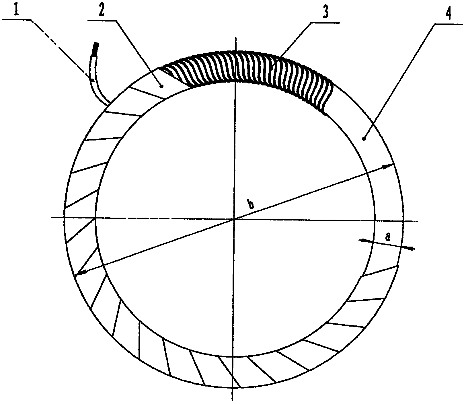
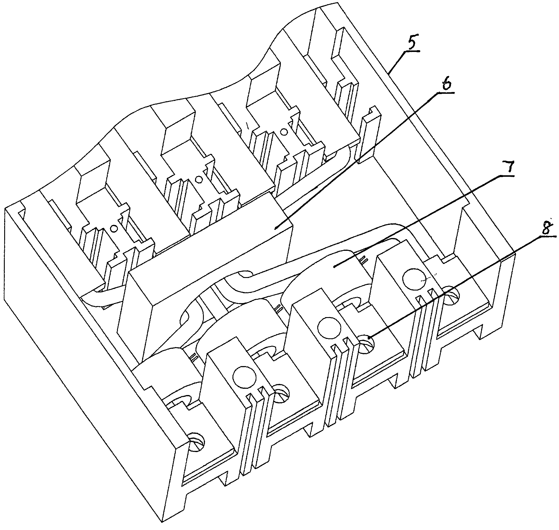
[0011] The present invention will be described in detail below in conjunction with embodiments and with reference to the drawings: see figure 1 versus figure 2 , The following four measures are taken in this leakage circuit breaker outgoing terminal phase loss protection method:

[0012] (1) Selection of acquisition signal: Select the current change of the leakage circuit breaker without return current after the phase line is missing at the outlet end of the leakage circuit breaker as the signal source, collect the current signal, and set the operating current of the leakage circuit breaker ≤1A or ≤500mA for the opening action Critical value

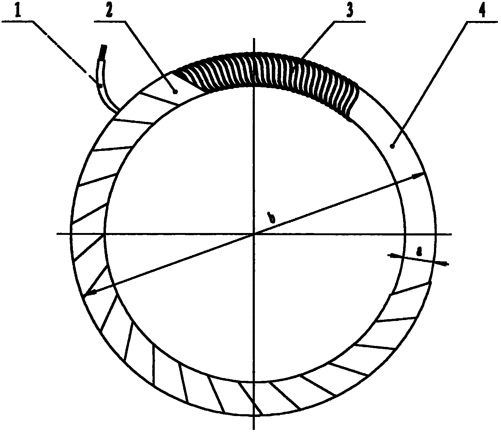
[0013] (2) Production of current sensing element: the toroidal core, namely the plastic ring 4, is made of high-temperature resistant and flame-retardant engineering plastics, and a single densely-turned enameled wire layer 3 is wound on the outside. The enameled wire layer 3 is wrapped with an insulating tape layer 2, and the two ends of t...


PUM


Abstract

A lead-out end phase-failure protection method for a leakage circuit breaker adopts the following four measures: the first measure is the selection of an acquisition signal, namely, a lead-out end phase-failure current change is acquired as a signal; the second measure is the fabrication of current inductive elements, namely, a plastic loop (4) is used as a core, an enameled wire layer (3) and an insulating tape layer (2) are wound around the exterior of the core, and the two ends of the enameled wire are led out by two insulating leads 1; the third measure is the installation of a leakage circuit breaker with a lead-out end phase-failure protection function, namely, three current inductive elements are respectively arranged on three live wires between a zero sequence mutual inductor (6) and a lead-out column (8) in a common leakage circuit breaker (5); and the fourth measure is the setting of a lead-out end phase-failure protection procedure for the leakage circuit breaker, namely, the current inductive elements collect the current change information caused by the phase failure, transfer to an AD conversion processor and then send to a microprocessor, the microprocessor instructs to alarm and implements break-brake protection after comprehensive analysis. The method solves the lead-out end phase-failure problem that is long for being solved and cannot be solved and fills in the gap in the field of phase failure protection.

Description

Technical field [0001] The invention relates to an emergency protection method for a low-voltage power grid, in particular to a method for expanding the protection range of a signal collected by a phase loss at an outlet terminal by improving a general leakage circuit breaker and installing a new type of current sensing element. Background technique [0002] At present, the leakage circuit breakers on the general low-voltage power grid have multiple functions such as overvoltage protection, overload protection, undervoltage protection, overcurrent protection, and phase loss protection. These protections are all related to the collection of information about the incoming power grid. It is protected after the opening action occurs. In recent years, the supervisory unit of the electric power department and the user units such as the telecommunications department have repeatedly proposed to realize the lack of phase protection at the outlet end of the leakage circuit breaker. In low...

Claims


Application Information

Patent Timeline
Patent Type & Authority Applications(China)
IPC IPC(8): H02H7/26H02H3/253H02H3/34H01H83/12H01H83/14
Inventor 余永辉潘春荣
Owner 浙江豪顿电气有限公司
Learn More