Extractor hood

A range hood and smoke technology, applied in the direction of removing oil fume, mechanical equipment, thin plate connection, etc., can solve problems such as loosening, achieve the effect of simple cleaning and improve appearance and shape

Active Publication Date: 2011-10-19
BSH BOSCH & SIEMENS HAUSGERAETE GMBH
View PDF7 Cites 5 Cited by
  • Summary
  • Abstract
  • Description
  • Claims
  • Application Information

AI Technical Summary

Problems solved by technology

In addition, there is always the risk of loosening of screw connections due to vibrations, which occur, for example, when transporting cooker hoods

Method used


Image

  • Extractor hood
  • Extractor hood
  • Extractor hood

Examples


Embodiment Construction

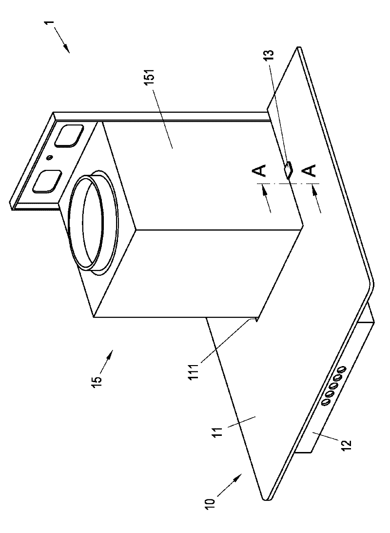
[0037] exist figure 1 An embodiment of the cooker hood 1 according to the invention is shown schematically in a perspective view. The range hood includes a fan box 15 having a box-shaped channel 151 . A pipe connection is inserted on the upper side of this channel 151 as an air outlet. The fan box 15 is surrounded on three sides by the fume cover 10 at its lower end. The smoke cover 10 includes a smoke cover plate 11 and a visible cover 12 . In the embodiment shown, the fume shield 11 is a single-piece flat glass element. A recess 111 is provided centrally in the rear side of the fume shield 11 , in which recess a channel 151 of the fan box 15 is accommodated. The smoke hood panel 11 is held on a visible hood 12 . In the illustrated embodiment, the visible cover 12 is a sheet-metal frame, in the back of which a central recess 121 is likewise provided. The recesses 111 in the smoke hood panel 11 coincide with the recesses 121 in the visible hood 12 , that is to say they a...


PUM


Abstract

The invention relates to an extractor hood. The extractor hood comprises a smog cover panel (11) having a recess (111) for accommodating a channel (155), a visible cover (12) having a recess (121) for accommodating a channel (151) and at least a fixing element (13) used for fixing the smog cover panel (11) on the visible cover (12). The extractor hood is characterized in that The fixing element (13) encloses and clamps at least a part of the edge of the smog cover panel (11) and at least a part of the edge of the visible cover (12).

Description

technical field [0001] The invention relates to a cooker hood according to the preamble of claim 1 . Background technique [0002] Currently, range hoods or chimneys are manufactured with one-piece or multi-piece fume hoods. In this case, the fume shield can be made of glass, for example. The fume hood is connected to the chimney via a carrier element. [0003] Such a hood is described in DE 10 208 017 286 A1, in which the fume hood is fixed on the carrier part by at least one fastening element, wherein the fume hood can be loosened or tensioned without tools for assembly and disassembly. Fixed elements. In this case, screws are used as fastening elements with union nuts which can be screwed onto them. The bolts pass through openings provided in the carrier part. Furthermore, the bolts pass through openings provided in the fume shield. The carrier part and the fume shield are fastened to one another in order to pass the screw through two coincident openings in the carr...

Claims


Application Information

Patent Timeline
Patent Type & Authority Applications(China)
IPC IPC(8): F24C15/20F16B5/00
CPCF24C15/20
Inventor J·克莱姆J·莱斯M·里希特H·斯瓦特
Owner BSH BOSCH & SIEMENS HAUSGERAETE GMBH
Why Eureka
Try Eureka