Particle trap for a plasma source

一种颗粒捕集器、远程等离子源的技术,应用在等离子体、化学仪器和方法、使气体介质与气体介质反应的方法等方向,能够解决污染等离子产生器颗粒等问题,达到再组合少、生产停机时间少、高生产率的效果

Inactive Publication Date: 2011-10-12
MKS INSTR INC
View PDF3 Cites 1 Cited by
  • Summary
  • Abstract
  • Description
  • Claims
  • Application Information

AI Technical Summary

Problems solved by technology

[0004] A known problem in the field of plasma generation is the general generation of particles that can, for example, contaminate the plasma generator or the plasma chamber coupled to the plasma chamber output

Method used


Image

  • Particle trap for a plasma source
  • Particle trap for a plasma source
  • Particle trap for a plasma source

Examples


Embodiment Construction

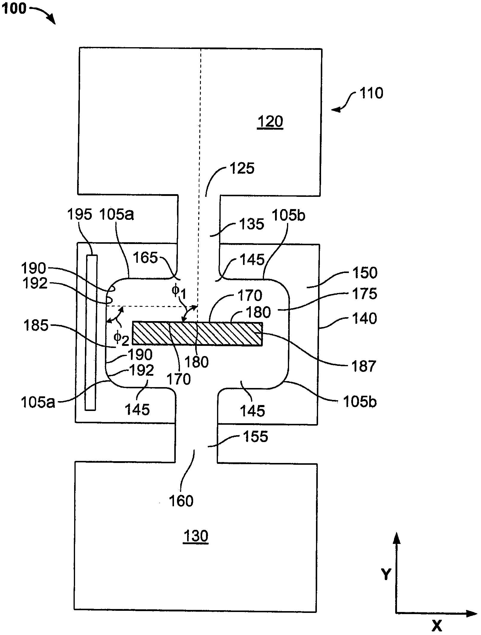
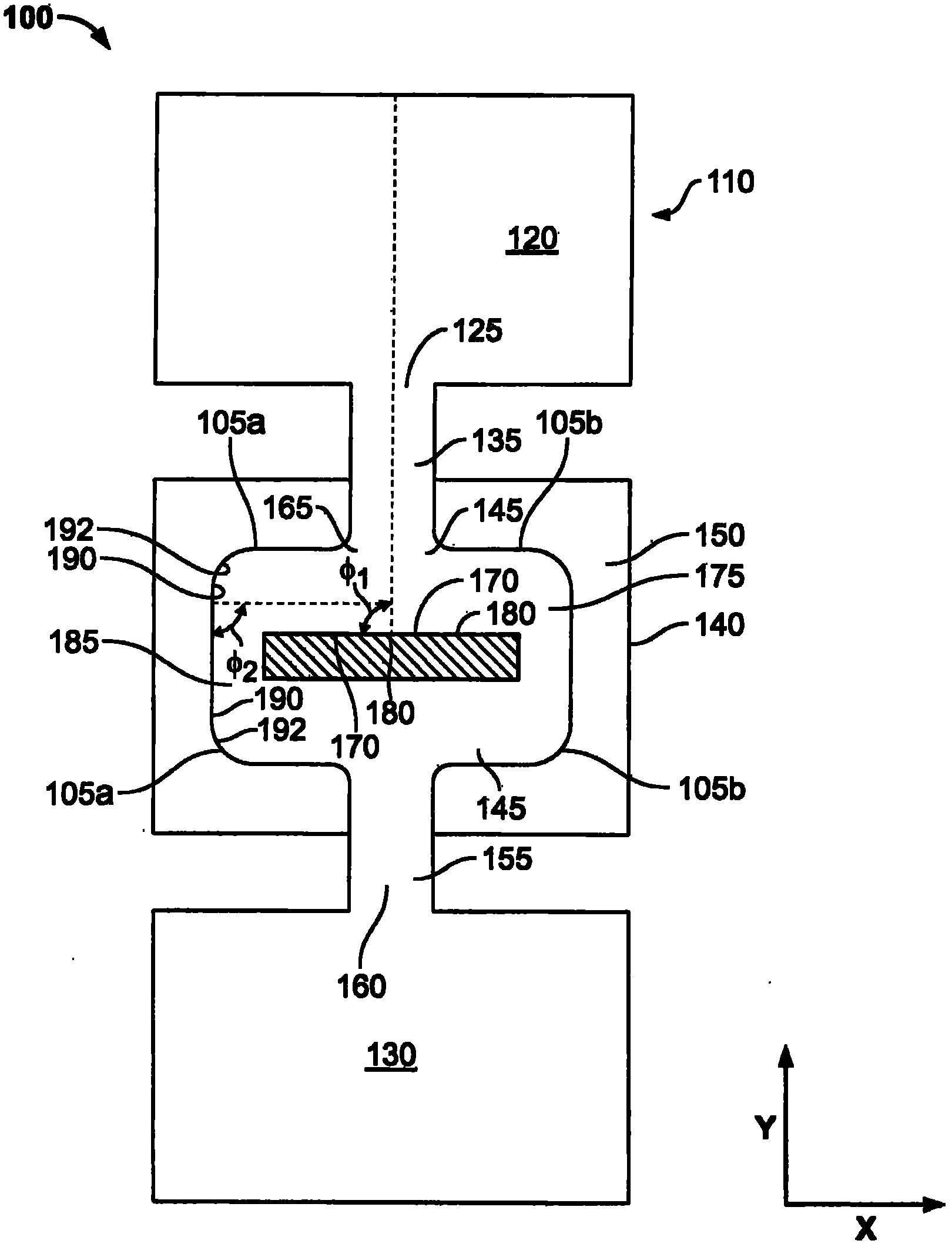
[0035] figure 1 is a schematic cross-sectional view of a plasma generation system 100 according to an exemplary embodiment of the present invention. The system 100 includes a remote plasma source 110 , a processing chamber 130 , and a particle trap 140 . The outlet 125 of the remote plasma source 110 is coupled to the inlet 135 of the particle trap 140 . In certain embodiments, outlet 125 is directly coupled to inlet 135 . In some embodiments, the outlet 125 is indirectly coupled to the inlet 135 by, for example, a pipe or other suitable structure. In the chamber 120 of the plasma source 110, for example, the plasma gas (such as O 2 , N 2 , Ar, NF 3 、H 2 and He) or a mixture of gases is applied with a sufficient potential to ionize at least a portion of the gas in chamber 120 to generate a plasma. The plasma is used to activate other gases introduced into the chamber 120 of the plasma source 110, placing the other gases in an active state such that the gases have, for e...


PUM


Abstract

A particle trap for a remote plasma source includes a body structure having an inlet for coupling to a chamber of a remote plasma source and an outlet for coupling to a process chamber inlet. The particle trap for a remote plasma source also includes a gas channel formed in the body structure and in fluid communication with the body structure inlet and the body structure outlet. The gas channel can define a path through the body structure that causes particles in a gas passing from a first portion of the channel to strike a wall that defines a second portion of the gas channel at an angle relative to a surface of the wall. A coolant member can be in thermal communication with the gas channel.

Description

technical field [0001] The present invention generally relates to plasma generation and processing apparatus. In particular, the present invention relates to methods and apparatus for removing contaminating particles from reactive gases. Background technique [0002] Plasma is often used to activate gases placing them in an activated state, which gives the gases enhanced chemical reactivity. In some cases, these gases are activated to produce dissociated gases containing ions, free radicals, atoms and molecules. Dissociated gases are used in a variety of industrial and scientific applications, including processing solid materials such as semiconductor wafers, powders, and other gases. The properties of the reactive gas and the conditions under which the material is exposed to the gas vary widely depending on the application. Sometimes considerable power is required in the plasma to dissociate. [0003] The plasma source is passed, for example, to a plasma gas (such as O ...

Claims


Application Information

Patent Timeline
Patent Type & Authority Applications(China)
IPC IPC(8): H01J37/32
CPCH01J37/32357H01J37/32871Y10S55/15Y10T29/4935
Inventor A·沙基X·陈A·考韦D·布特纳W·R·安特雷邵守谦
Owner MKS INSTR INC
Why Eureka
Try Eureka