
Medium wave infrared continuous zoom lens

A zoom lens and infrared technology, applied in the optical field, can solve the problems of inability to meet the 640×512 yuan, increase the load, etc., and achieve the effect of good zooming effect, reducing influence and improving image quality.

Active Publication Date: 2011-10-12
11TH RES INST OF CHINA ELECTRONICS TECH GROUP CORP
View PDF14 Cites 35 Cited by
  • Summary
  • Abstract
  • Description
  • Claims
  • Application Information

AI Technical Summary

Problems solved by technology

The zoom lenses reported above are all based on a 320×240 element, a cooled detector with a pixel size of 30um×30um, which cannot meet the image quality requirements of a 640×512 element, with a pixel size of 25um×25um.
The 20 times continuous zoom lens realized by 7 lenses with a focal length of 14mm-280mm was reported by Xu Zhaodong and others from China First Airline Luoyang Electro-optical Equipment Research Institute in "Infrared and Laser Engineering Journal", Volume 36, No. 5, Page 619-621. The detector used is a 640×512 element cooling detector with a pixel size of 15um×15um, but there are 3 lenses involved in zooming. When the system zooms, these 3 lenses need to move at the same time, which undoubtedly increases the Load during system zooming

Method used


Image

  • Medium wave infrared continuous zoom lens
  • Medium wave infrared continuous zoom lens
  • Medium wave infrared continuous zoom lens

Examples


Embodiment Construction

[0058] The present invention will be described in further detail below in conjunction with the accompanying drawings and specific embodiments.

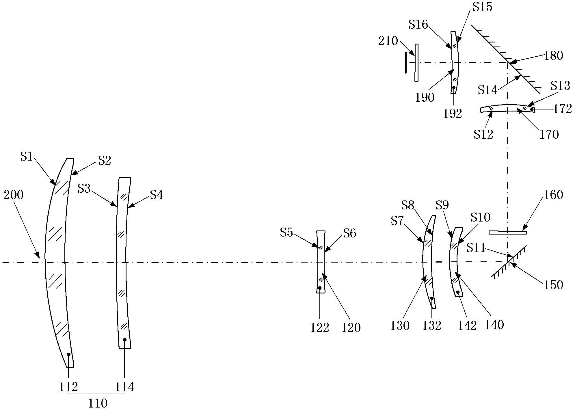
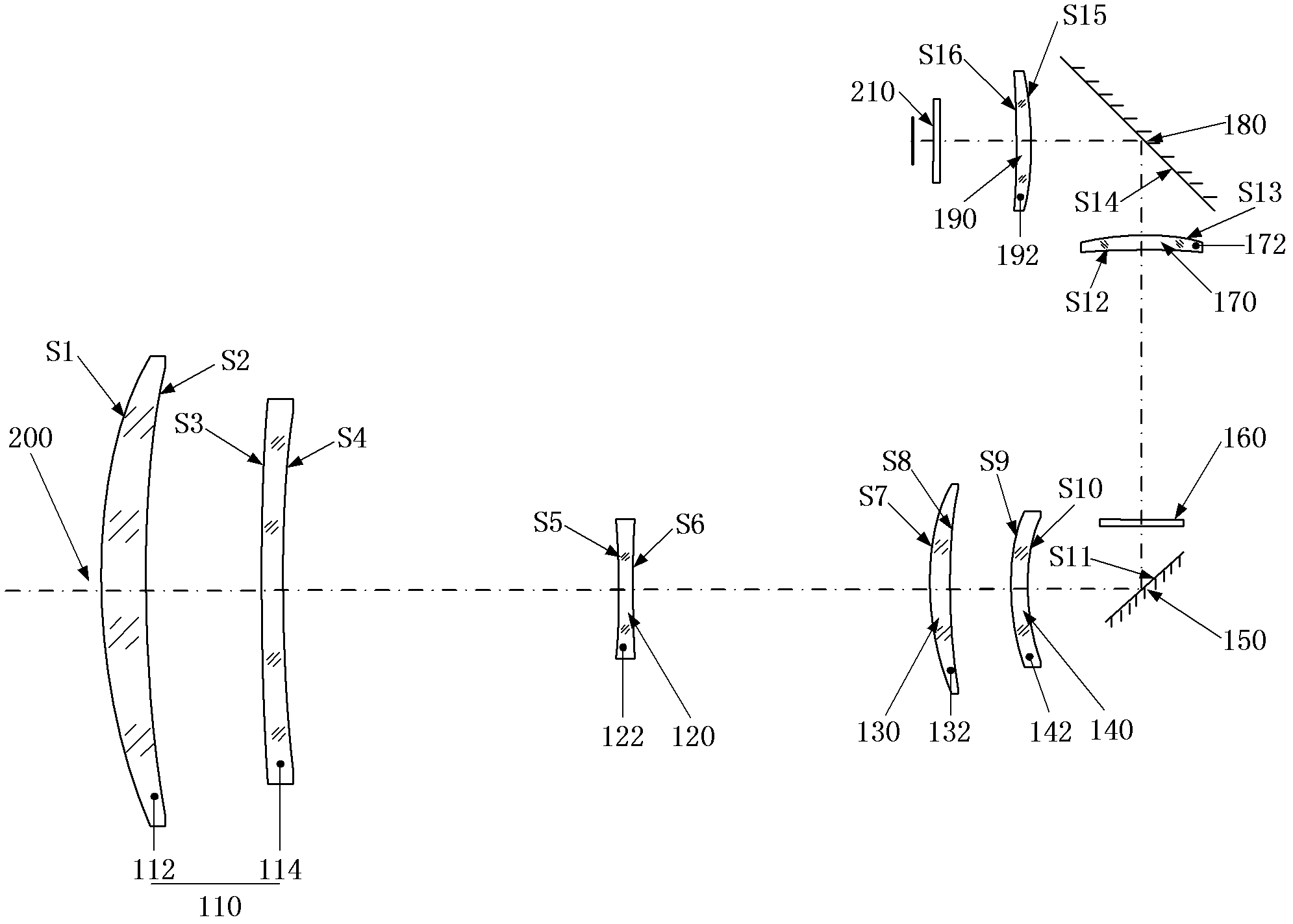
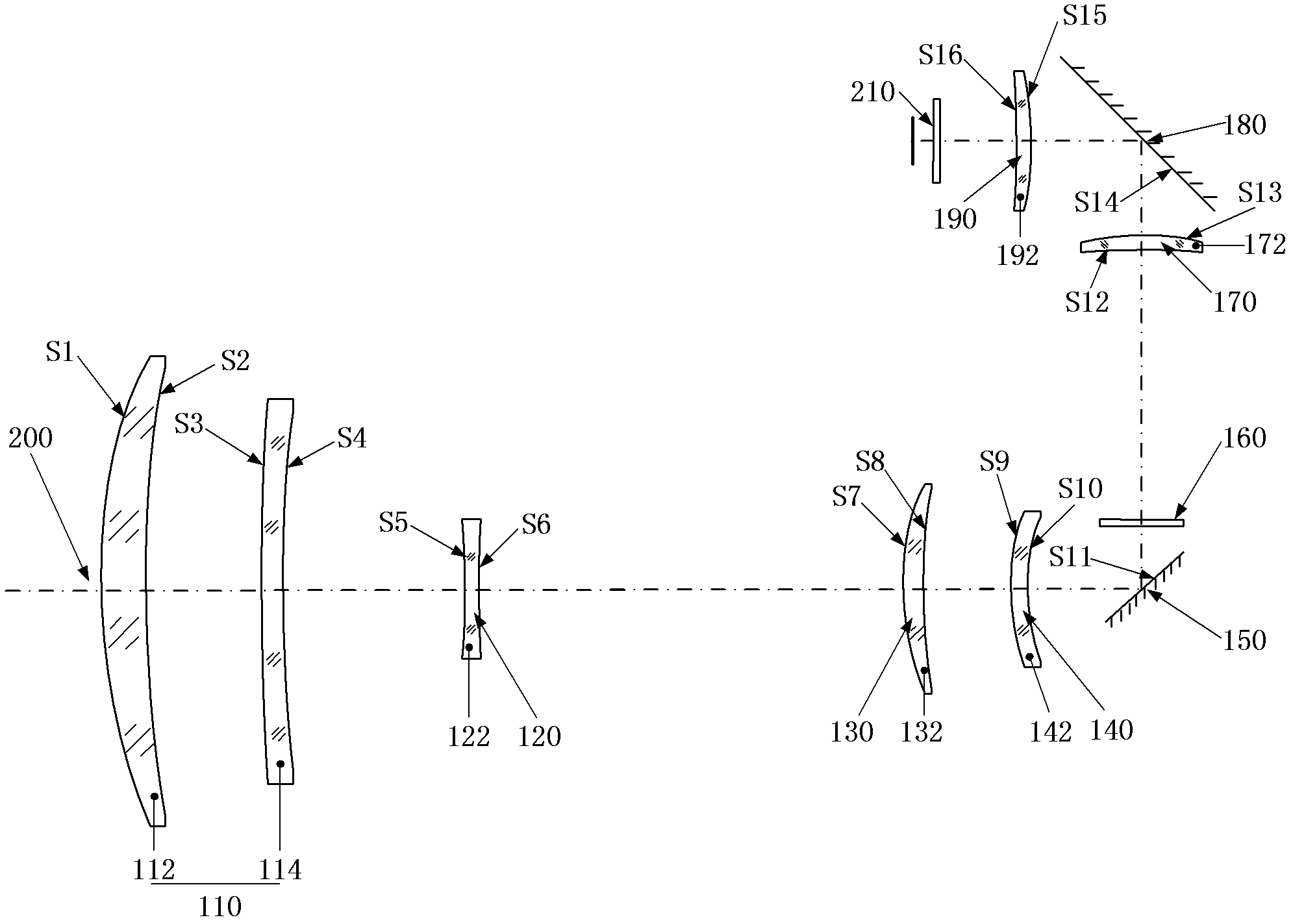
[0059] figure 1 , figure 2 , image 3 They are respectively schematic diagrams of the mid-wave infrared continuous zoom lens in the telephoto, medium-focus and short-focus positions of the present invention.

[0060]As shown in the figure, the mid-wave infrared continuous zoom lens of the present invention includes in sequence from the object side to the imaging side: a first lens group 110 with positive diopter, a second lens group 120 with negative diopter, and a third lens group with positive diopter 130, the fourth lens group 140 with negative diopter, the first reflector 150 for refracting the optical path, the flat panel reference source 160 for background correction, the fifth lens group 170 with positive refraction, used for refraction The second reflection mirror 180 for the optical path has a sixth lens group 190 of posi...


PUM


Abstract

The invention discloses a medium wave infrared continuous zoom lens. The medium wave infrared continuous zoom lens comprises a first lens group with positive diopter, a second lens group with negative diopter, a third lens group with positive diopter, a fourth lens group with negative diopter, a first reflector for turning back a light path, a flat plate reference source for correcting a background, a fifth lens group with positive diopter and a sixth lens group with positive diopter from an object space to an image space, wherein the first lens group serving as a front fixing group comprisesa crescent silicon positive lens of which the convex surface faces the object side and a crescent germanium negative lens of which the convex surface faces the object side; the second lens group is used as a zoom group; the third lens group is used as a compensation group; the fourth lens group is used as a rear fixing group; the fifth lens group is used as a relaying group; and the sixth lens group is used as a focusing group. The medium wave infrared continuous zoom lens can be applied to 640*512-element or even larger surface array refrigeration medium wave detectors; and the medium wave infrared continuous zoom lens has a simple structure and low motion charge; and only two lenses move during zooming.

Description

technical field [0001] The invention belongs to the field of optical technology, in particular to a mid-wave infrared continuous zoom lens. Background technique [0002] In recent years, the application breadth and depth of infrared imaging technology have made considerable progress. Due to its high sensitivity and its price, the medium-wave cooling detector has obvious advantages over the same type of long-wave detector. Military and related civilian fields such as intelligence and reconnaissance have broad application prospects. In many special occasions, infrared dual-field or even three-field lenses can no longer meet the application requirements. One of the core components of the mid-wave infrared continuous zoom imaging system is the mid-wave infrared zoom lens, which achieves continuous zoom by moving different lens groups while maintaining a clear image plane, enabling large field of view to search for targets, tracking targets during zooming, and small field of vie...

Claims


Application Information

Patent Timeline
IPC IPC(8): G02B15/16
Inventor 骆守俊吴玮王弘韬徐明轩何伍斌温庆荣
Owner 11TH RES INST OF CHINA ELECTRONICS TECH GROUP CORP
Learn More