


Quick Research
Generate reliable direction feasibility study reports for your R&D in just a few steps.

Technical Q&A
Discover and master advanced knowledge NOW. Basics, ideas, possibilities, all at once.

Find Solutions
As an expert in R&D theories, this can generate solutions to your technical problems instantly.

Evaluate Feasibility
Analyze your overall solution with one click, know your potential R&D risks in advance.

Monitor Landscape
Get weekly tech updates, stay abreast of the latest tech innovations and key insights.
Surface modification method of carbon material and application thereof in microbial fuel cell
A surface modification, fuel cell technology, applied in battery electrodes, circuits, electrical components, etc., to achieve the effects of high power output, low price, and reduced construction costs
- Summary
- Abstract
- Description
- Claims
- Application Information
AI Technical Summary
Problems solved by technology
Method used
Image

Examples
Embodiment 1
[0036] The first step: preparation and characterization of potassium dichromate activated graphite material
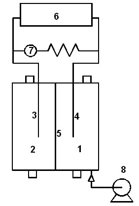
[0037] (1) Clean a graphite rod with a diameter of 6 mm and 200 mL of graphite particles with a particle size of 5×4 mm with deionized water and ethanol, and air-dry. Then, at room temperature, soak graphite rods and 150 mL of pretreated graphite particles in 0.1 mol / L potassium dichromate and concentrated sulfuric acid solution with a volume ratio of 2:1 for 5 hours, then rinse with deionized water, and let them dry in the air. Dry.
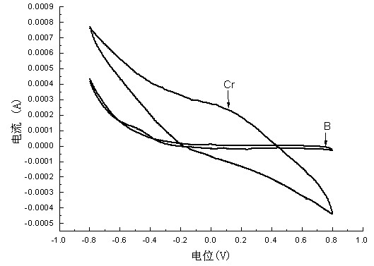
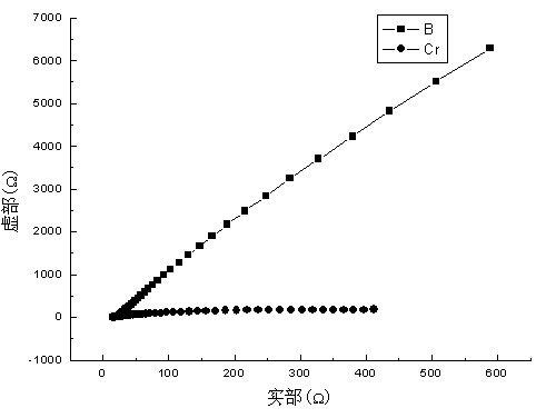
[0038] (2) Electrochemical tests were carried out on the graphite electrodes before and after activation: the electrochemical tests were carried out on the chemically activated electrodes using the traditional three-electrode system, that is, at room temperature using a Parstat 2273 electrochemical workstation, with 50mM phosphate buffer The solution (PBS) is the electrolyte, the calomel electrode (Hg / HgO electrode) is used as the refer...
Embodiment 2
[0046] The first step: preparation and characterization of potassium permanganate activated graphite material
[0047] (1) Clean a graphite rod with a diameter of 6 mm and 200 mL of graphite particles with a particle size of 5×4 mm with deionized water and ethanol, and air-dry. Put the graphite rod and 150mL pretreated graphite particles in the 0.1mol / L potassium permanganate and concentrated sulfuric acid solution with a volume ratio of 2:1 (single dichromate, permanganate, ferrate can be ) for 5 hours, rinsed with deionized water, and dried.
[0048] (2) Electrochemical tests were performed on the graphite electrodes before and after modification. The electrochemical test shows that the oxygen reduction current of the modified graphite electrode is significantly greater than that of the unactivated electrode in the cyclic voltammetry test, indicating that the oxygen reduction ability of the activated electrode is enhanced.
[0049] Step Two: Microbial Fuel Cells
[0050] ...
PUM
 Abstract
Description
Claims
Application Information
 - R&D Engineer
- R&D Manager
- IP Professional
- Industry Leading Data Capabilities
- Powerful AI technology
- Patent DNA Extraction
Browse by: Latest US Patents, China's latest patents, Technical Efficacy Thesaurus, Application Domain, Technology Topic, Popular Technical Reports.
© 2024 PatSnap. All rights reserved.Legal|Privacy policy|Modern Slavery Act Transparency Statement|Sitemap|About US| Contact US: help@patsnap.com