
Dielectric wall accelerator

An accelerator and medium technology, applied in linear accelerators, accelerators, electrical components, etc., can solve the problems of pulse distortion, medium wall acceleration, acceleration gradient, etc., and achieve the effect of strong beam current, high acceleration gradient and low cost

Inactive Publication Date: 2011-09-28
四川省科学城久远磁性材料有限责任公司
View PDF4 Cites 0 Cited by
  • Summary
  • Abstract
  • Description
  • Claims
  • Application Information

AI Technical Summary

Problems solved by technology

[0014] The purpose of the present invention is to overcome the shortcomings of the existing dielectric wall acceleration, and provide a shortcoming that overcomes the magnetic field formed by the pulse current that will cause interference in the adjacent layer and cause pulse distortion, and the accelerated beam current is strong, the acceleration gradient is high, and the structure Simple, Inexpensive Dielectric Wall Accelerator

Method used


Image

  • Dielectric wall accelerator
  • Dielectric wall accelerator
  • Dielectric wall accelerator

Examples


Embodiment Construction

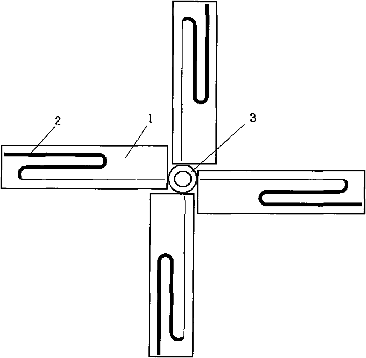
[0025] Examples of the present invention figure 1 , figure 2 As shown: the acceleration pulse forming device of a single acceleration unit is composed of four dielectric plates 1, each dielectric plate 1 is coated with metal electrodes 2 on the upper and lower sides, and a high-voltage input terminal is arranged in the middle of the dielectric plate 1, and the high-voltage input terminal is connected to one of the dielectric plates 1 A photoconductive switch is connected between the metal electrodes 2, and each layer is composed of two dielectric flat plates 1 arranged symmetrically outside the medium beam pipe 3. The magnetic field formed by the bending direction of the metal electrodes 2 on the two symmetrical dielectric flat plates 1 The same, opposite directions; the angle between the two symmetrical dielectric plates 1 on the second layer is the same as that of the first layer outside the medium beam pipe 3, and the metal electrode 2 on the dielectric plate 1 on the left...


PUM


Abstract

The invention discloses a dielectric wall accelerator with strong accelerating beam current and high accelerating gradient. The dielectric wall accelerator comprises a sealed barrel and a dielectric beam pipeline in the middle of the barrel; an accelerating pulse forming device of an accelerating unit comprises dielectric flat plates, metal electrodes arranged on each dielectric flat plate, a high-voltage input end and a photoconductive switch, wherein each accelerating unit comprises at least two layers of accelerating pulse forming devices; each layer comprises two accelerating pulse forming devices which are symmetrically arranged outside the dielectric beam pipeline; and the magnetic fields generated along the bending directions of the metal electrodes arranged on the dielectric flat plates in the two symmetrical accelerating pulse forming devices have the same size and are opposite to each other. The accelerating pulse forming device makes the magnetic fields generated by a pulse current counteract each other in the center of the dielectric beam pipeline, while the generated electrical fields cooperate with each other, so that charged particles in the pipeline are accelerated and the defect that the magnetic fields generated by the pulse current interfere with each other in an adjacent layer to cause the pulse distortion is overcome; and the dielectric wall accelerator has the advantages of strong accelerating beam current, high accelerating gradient, simple structure and low cost.

Description

technical field [0001] The invention relates to a strong current particle accelerator, in particular to a medium wall accelerator with strong accelerated beam current and high accelerated gradient. Background technique [0002] After more than one hundred years of development, accelerator technology has made great progress. Accelerators of various structures play a very important role in the fields of national economic development, scientific research, medical and health care, and national defense construction. However, the current accelerators all have their shortcomings, such as low beam intensity, low acceleration gradient, or high cost, often costing billions or even tens of billions of yuan. [0003] Dielectric wall accelerator is a new type of high-gradient and strong-current accelerator concept proposed in recent years. Compared with traditional accelerators, it has many excellent characteristics. It is used for flash X-ray photography, proton photography, subcritica...

Claims


Application Information

Patent Timeline
Patent Type & Authority Applications(China)
IPC IPC(8): H05H7/22H05H9/00
Inventor 罗安雄
Owner 四川省科学城久远磁性材料有限责任公司
Learn More