Method for controlling heliostat used for condensing of sunlight and device thereof

A control method and heliostat technology, which is applied in the field of solar concentrating heliostats, can solve the problems of focus position shifting, concentrating efficiency reduction, etc., achieve high area configuration efficiency, and realize the effect of area configuration efficiency

Inactive Publication Date: 2013-12-04
MITSUI ENG & SHIPBUILD CO LTD
View PDF1 Cites 0 Cited by
  • Summary
  • Abstract
  • Description
  • Claims
  • Application Information

AI Technical Summary

Problems solved by technology

[0010] However, for the heliostat described in Patent Document 1, as in Patent Document 1, image 3 As shown, the solar light is tracked by rotating on the X-axis and the Y-axis, and the facet mirror is moved around the intersection of the X-axis and the Y-axis of the heliostat. Therefore, there is a problem that various A phenomenon in which the position of the focal point formed by the reflected light of the small flat mirror shifts (coma aberration), and the light-gathering efficiency decreases

Method used


Image

  • Method for controlling heliostat used for condensing of sunlight and device thereof
  • Method for controlling heliostat used for condensing of sunlight and device thereof
  • Method for controlling heliostat used for condensing of sunlight and device thereof

Examples


Embodiment 1

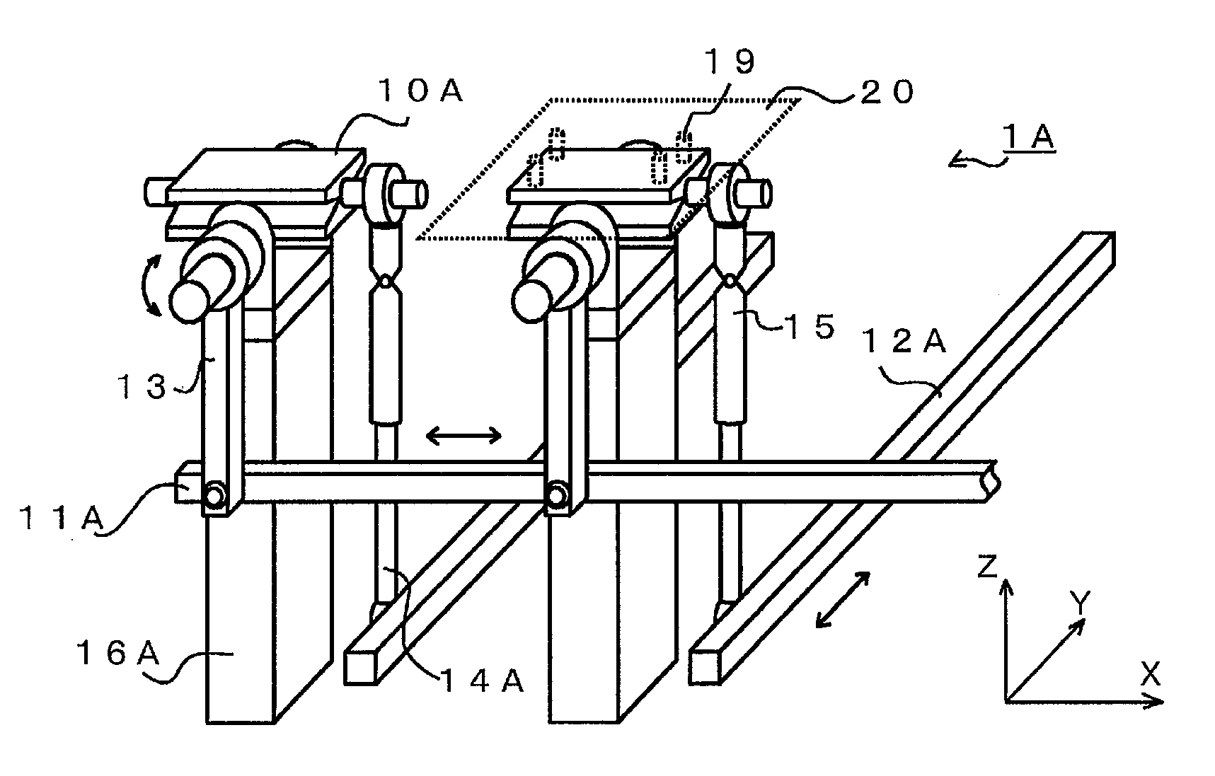
[0054] figure 1 A partially enlarged view showing a heliostat 1A as a first embodiment of the present invention, figure 2 A perspective view showing a heliostat 1A composed of nine facet mirrors 20 . Each of the facet mirrors 20 is fixed to the tilt mechanism 10A by means of the facet mirror holder 19 , and the tilt mechanism 10A is provided on the stand 16A. In addition, the tilt mechanism 16A is connected in the X-axis direction by the X-axis link 11A via the X-axis arm portion 13, and is connected in the Y-axis direction by the Y-axis link 12A via the universal joint 15 and the cylinder mechanism 14A. Get up and move in tandem with each other. Here, the facet mirror 20 is adjusted in advance using the facet mirror holder 19 at an attachment angle so as to have a focal point at an arbitrary point.

[0055] figure 2 It is an example showing the case of combining a plurality of facet mirrors 20 as the heliostat 1A. Here, nine facet mirrors 20 are connected by links in t...

Embodiment 2

[0059] image 3 is a schematic front view showing a heliostat 1B as a second embodiment of the present invention, Figure 4 Represents a side profile view. The heliostat 1B is configured such that a facet mirror 20 having a deflection mechanism 10B below is centered on a Y-axis link 12B. image 3 Rotate in the left-right direction shown. A plurality of skew mechanisms 10B are connected together by an X-axis link 11B as a link mechanism, and the connection is located at image 3 A plurality of facet mirrors 20 in the left-right direction (X-axis direction) undulate in linkage.

[0060] In addition, if Figure 4 shown, with image 3 The X-axis direction is perpendicular to the Y-axis direction (relative to image 3 The inner near-front direction of the paper or Figure 4 The ups and downs in the left and right directions) can be realized by linking the plurality of facet mirrors 20 to the Y-axis link 12B, respectively.

[0061] According to this embodiment, since the lin...

Embodiment 3

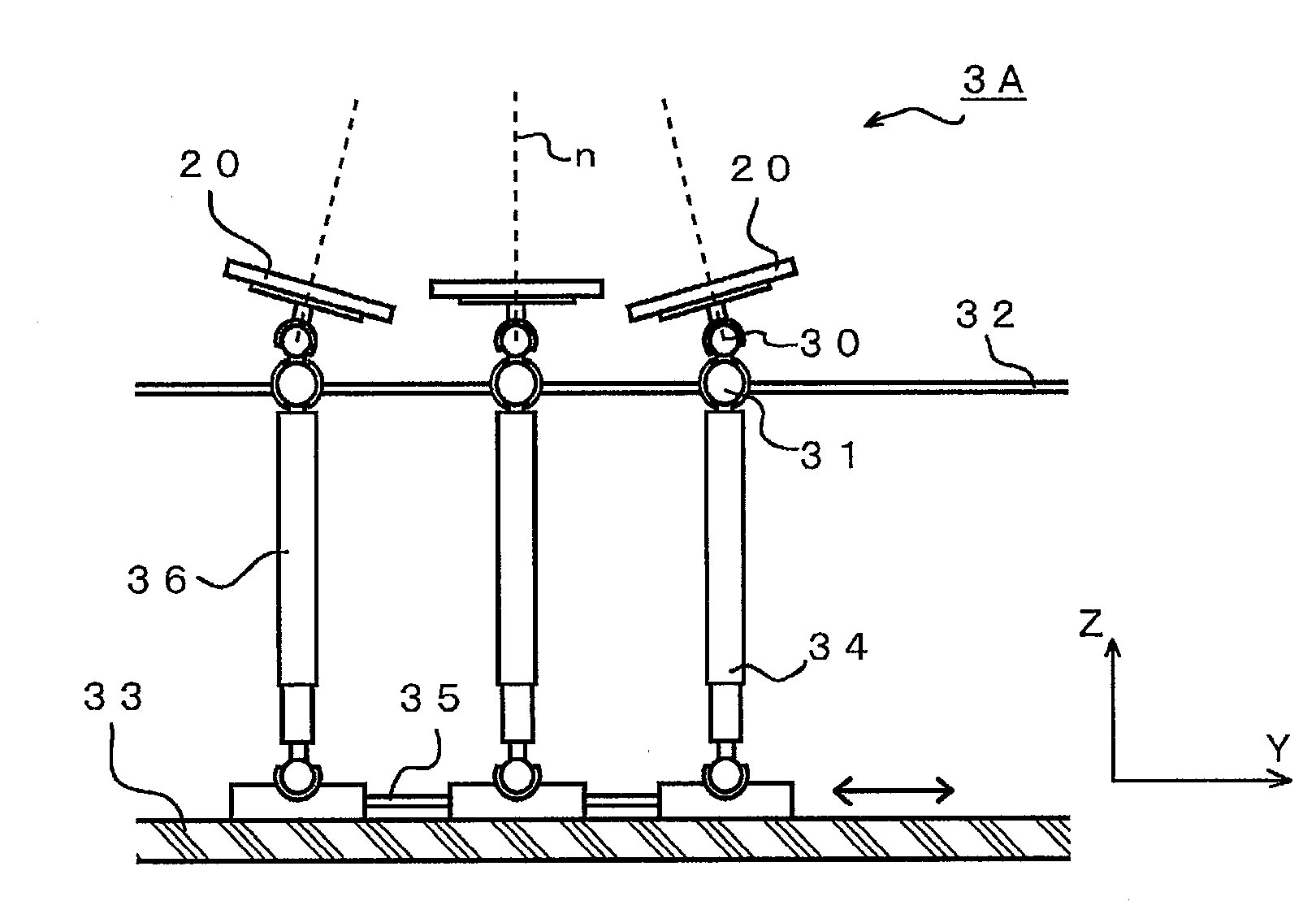
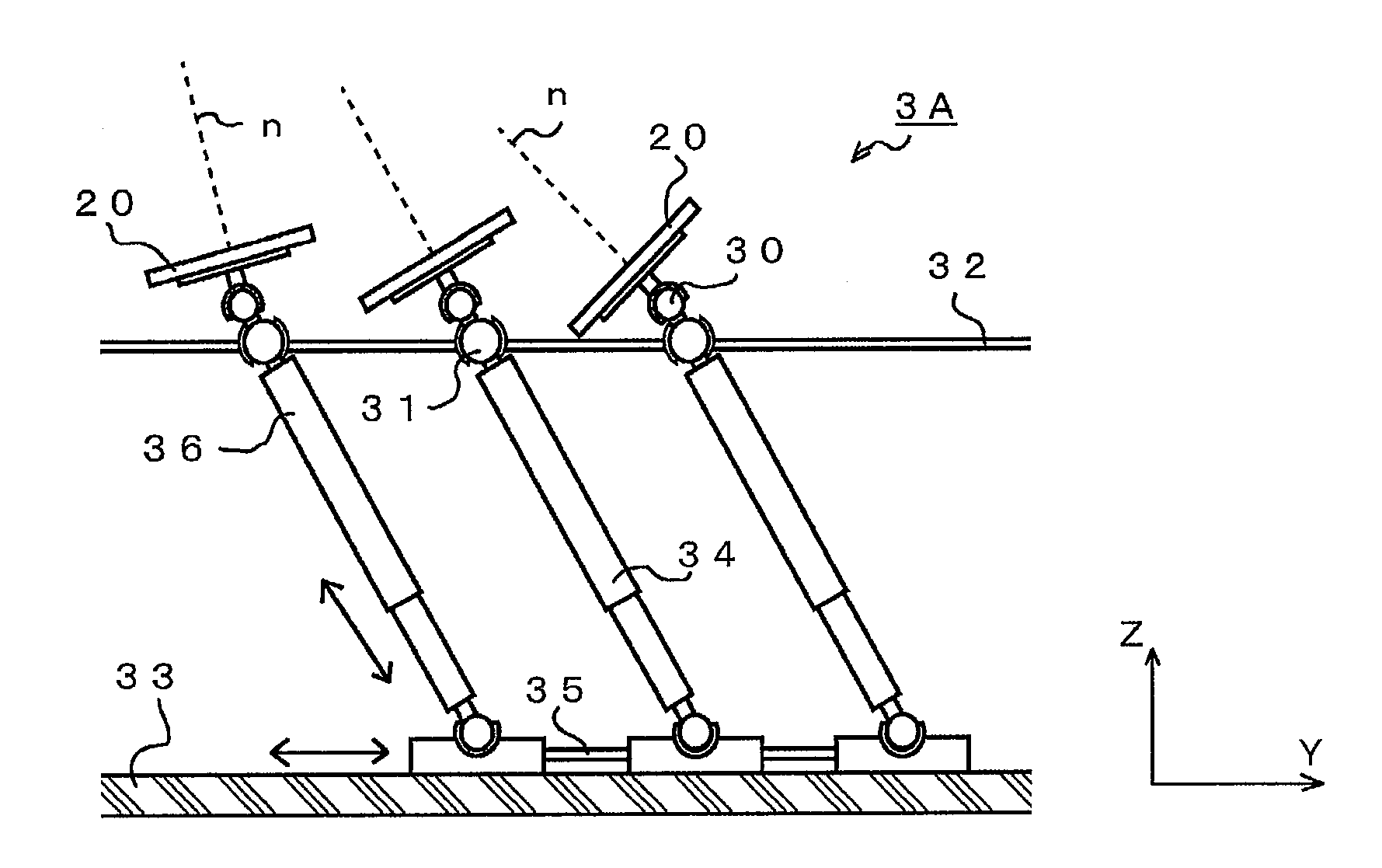
[0063] Figure 5 Showing the outline of a heliostat 3A as a third embodiment of the present invention, Figure 6 Represents what it looks like when the sun is being tracked. The heliostat 3A is provided with a plurality of facet mirrors 20 having a columnar support member 36 below, and the plurality of facet mirrors 20 are arranged to have a focal point. The head of the joint is rotatably supported by an intermediate fixing plate 32 via a rotation mechanism 31 . The rotation mechanism 31 of the head can also be realized by a joint with two degrees of freedom other than the above-mentioned spherical joint.

[0064] The upper part of the support member 36 is connected with the facet mirror 20 via the installation angle adjustment mechanism 30. When installing the heliostat, the installation angle of the facet mirror 20 is adjusted by the installation angle adjustment mechanism 30, so that the reflection of the plurality of facet mirrors 20 Light has a focal point at an arbitr...


PUM


Abstract

Provided are a method for controlling a heliostat used for collecting of sunlight and a device of the method that achieve: a high sunlight collecting efficiency with a high light collecting rate by allowing no deviation of a light collecting point (a focal point) of sunlight; and a high area arrangement efficiency by having such a configuration in which no rotation by means of a rotation mechanism is carried out. The method is a method for controlling a heliostat being used for collecting of sunlight and having multiple reflecting mirrors in a way that the heliostat tracks the sun in motion, reflects sunlight, and collects the sunlight at a predetermined focal point. The method includes: a step of adjusting the multiple reflecting mirrors so that the multiple reflecting mirrors have a focal point at a predetermined distance; and a step of controlling the multiple reflecting mirrors to track the sun while light beams reflected from the reflecting mirrors have a focal point at an arbitrary point, the multiple reflecting mirrors being configured to tilt in conjunction with each other. In the method, while maintaining a state where the coordinates of predetermined points of the respective reflecting mirrors are fixed, the reflecting mirrors are operated in conjunction with each other.

Description

technical field [0001] The present invention relates to a control method and device for a solar concentrating heliostat for tracking the sun and concentrating reflected light on an arbitrary point (focus). Background technique [0002] In recent years, the depletion of petroleum resources and the rise in prices have caused concern. In addition, research has been conducted on shifting from petroleum resources, which is one of the causes of global warming, to new energy sources. As one of the new energy sources, there is solar thermal power generation which condenses sunlight and uses it as energy. [0003] In this solar thermal power generation, a heliostat that condenses sunlight is composed of a plurality of reflectors (facet mirrors), and is configured to reflect and condense sunlight to a heat receiving part, etc., and generate electricity using the heat. Alternatively, a large reflector (central reflector) can be configured as a central reflector type solar thermal powe...

Claims


Application Information

Patent Timeline
Patent Type & Authority Patents(China)
IPC IPC(8): F24J2/38F24J2/16G02B5/08G02B7/182F24S23/77F24S50/20
CPCF24J2/542G02B7/1827Y02E10/46F24J2002/5468G02B7/183F24J2002/5451F03G6/06G02B19/0042F24J2/16Y02E10/47F24J2/38G02B19/0019F24J2002/5489G02B19/008F24J2/5424F24S30/455F24S2030/17F24S50/20F24S30/452F24S2030/131F24S2030/136F24S23/77F24S30/45F03G6/063
Inventor 江泽一明川口隆
Owner MITSUI ENG & SHIPBUILD CO LTD
Why Eureka
Try Eureka