
Vehicle lights and vehicles

A vehicle lamp and LED chip technology, which is applied in the direction of headlights, road vehicles, vehicle parts, etc., can solve the problem of low design freedom, improve design freedom, reduce luminosity deviation and color deviation, and improve light distribution efficiency effect

Active Publication Date: 2020-09-25
ZKW GRP GMBH
View PDF5 Cites 0 Cited by
  • Summary
  • Abstract
  • Description
  • Claims
  • Application Information

AI Technical Summary

Problems solved by technology

[0007] On the other hand, the light source used in the vehicle lamp in the prior art is fixed, so there is a problem that the degree of freedom of design is low

Method used


Image

  • Vehicle lights and vehicles
  • Vehicle lights and vehicles
  • Vehicle lights and vehicles

Examples


Embodiment Construction

[0038] Hereinafter, the embodiments disclosed in this specification will be described in detail with reference to the drawings, and the same reference numerals will be assigned to the same or similar constituent elements regardless of the reference numerals, and repeated descriptions of these elements will be omitted. The suffixes "module" and "part" of the structural elements used in the following description are given or used in combination only for the convenience of writing the description, and do not have meanings or functions that distinguish each other. In addition, in the process of describing the embodiments disclosed in this specification, if it is judged that the detailed description of related known technologies will obscure the gist of the embodiments disclosed in this specification, the detailed description will be omitted. It should be understood that the accompanying drawings are only for the convenience of understanding the embodiments disclosed in this specifi...


PUM


Abstract

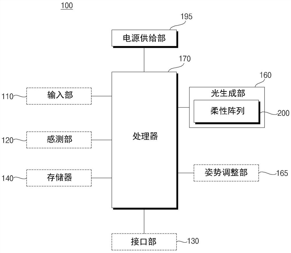
The present invention relates to a lamp for vehicles, comprising: a flexible array configured with a plurality of micro LED chips; a first lens that allows the path of light generated by the micro LED chips to penetrate through the flexible array and has at least two The plurality of micro LED chips of the shape form a plurality of groups of micro LED chips.

Description

technical field [0001] The present invention relates to a vehicle lamp and a vehicle. Background technique [0002] A vehicle is a device that moves in a direction desired by a user riding on it. As a representative example, an automobile can be exemplified. [0003] There are various lamps installed in the vehicle. For example, a vehicle is provided with a head lamp, a rear combination lamp, and a fog lamp. [0004] Such vehicle lamps are classified into lamps for ensuring the visibility of passengers (for example, headlights and fog lamps) and lamps for transmitting simple signals (for example, rear combination lamps). [0005] Various types of chips can be used as light sources of various lamps included in the vehicle. [0006] In recent years, researches on using a plurality of micro LED chips as light sources of vehicle lamps have been actively carried out. [0007] On the other hand, the light source used in the conventional vehicle lamp is fixed, so there is a pr...

Claims


Application Information

Patent Timeline
Patent Type & Authority Patents(China)
IPC IPC(8): F21K9/69F21V5/04F21V19/00F21Y115/10F21W107/10
CPCF21V5/04F21V19/0015F21K9/69F21Y2115/10F21W2107/10F21Y2107/20F21S41/147F21S41/153F21S41/176F21S41/00F21S41/141F21S41/275F21S41/32F21W2107/00B60Q1/20F21S41/285F21S41/657F21S43/14F21S43/26H01L25/0753H01L25/0756H01L33/507H01L33/508H01L33/60H01L33/62
Inventor 赵胄雄
Owner ZKW GRP GMBH
Learn More