
Energy-saving high-efficiency purification system for industrial volatilizable organic pollutant

An organic pollutant and energy-saving technology, which is applied in the field of energy-saving industrial volatile organic pollutant high-efficiency purification systems, can solve the problems of low purification rate of catalytic combustion bed, deactivation of catalyst, shortened service life of catalyst, etc., so as to improve self-sustained combustion. The effect of stability, improving catalytic purification rate and reducing heat loss

Inactive Publication Date: 2013-03-20
NANTONG ZHI HANG MECHANICAL & ELECTRICAL TECH CO LTD
View PDF7 Cites 0 Cited by
  • Summary
  • Abstract
  • Description
  • Claims
  • Application Information

AI Technical Summary

Problems solved by technology

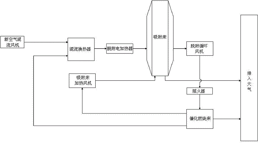
[0002] The industrial volatile organic pollutant purification system currently mainly includes, including mixed flow heat exchanger, fresh air mixed flow fan, catalytic combustion bed, desorption electric heater, desorption circulation fan and adsorption bed, the first air outlet of catalytic combustion bed and new The air outlet of the air mixed flow fan is connected to the air inlet of the mixed flow heat exchanger through pipes, and the air outlet of the mixed flow heat exchanger is connected to the desorption circulating fan through the desorption electric heater and the adsorption bed. Although this system has a certain purification effect, it has the following problems: 1. Since the air heated up by the desorption electric heater needs to heat the adsorbent, adsorbate and the metal structure of the adsorption bed at the same time when it enters the adsorption bed, the metal structure of the adsorption bed consumes part of the heat energy, thus prolonging the desorption process. time, which reduces the desorption efficiency, especially in winter in the north, the heat energy loss is greater, the desorption time is longer, and the waste heat generated by catalytic combustion is not fully utilized, which will also increase the thermal pollution of the atmospheric environment; 2. Catalytic combustion The purification rate of the bed is relatively low, and the service life of the catalyst is short. The reason is that industrial volatile organic pollutants enter the catalytic combustion bed in the prior art from below and are discharged from the top. Heating effect is generated, so the upper area of ​​the overall catalytic bed is easy to exceed its allowable working temperature due to heat energy accumulation, causing the catalyst to lose its activity, resulting in a reduction in purification rate and a shortened service life of the catalyst; in addition, the direction of natural convection in the catalytic combustion process of industrial volatile organic pollutants It runs from bottom to top. When passing through the catalytic combustion bed, the exhaust gas begins to rise rapidly, resulting in a decrease in the contact time between the exhaust gas and the catalytic combustion bed, resulting in a decrease in the purification rate.
In summary, the above two reasons lead to high energy consumption, low purification rate, shortened service life of the catalyst, long desorption process time, low purification efficiency and high operating cost in the purification system of the entire prior art.

Method used


Image

  • Energy-saving high-efficiency purification system for industrial volatilizable organic pollutant
  • Energy-saving high-efficiency purification system for industrial volatilizable organic pollutant
  • Energy-saving high-efficiency purification system for industrial volatilizable organic pollutant

Examples


Embodiment Construction

[0021] The present invention will be further described in detail below through the specific examples, the following examples are only descriptive, not restrictive, and cannot limit the protection scope of the present invention with this.

[0022] An energy-saving high-efficiency purification system for industrial volatile organic pollutants, including a mixed-flow heat exchanger, a fresh air mixed-flow fan, a catalytic combustion bed, a desorption electric heater, a desorption circulation fan, and an adsorption bed. The outlet of the fresh air mixed-flow fan passes through The pipeline is connected to the air inlet of the mixed flow heat exchanger, and the air outlet of the mixed flow heat exchanger is connected to the air inlet of the catalytic combustion bed through the desorption electric heater, adsorption bed and desorption circulation fan. The innovation points are:

[0023] (1), the catalytic combustion bed comprises a catalytic bed body 21, an air inlet 15, an air outle...


PUM


Abstract

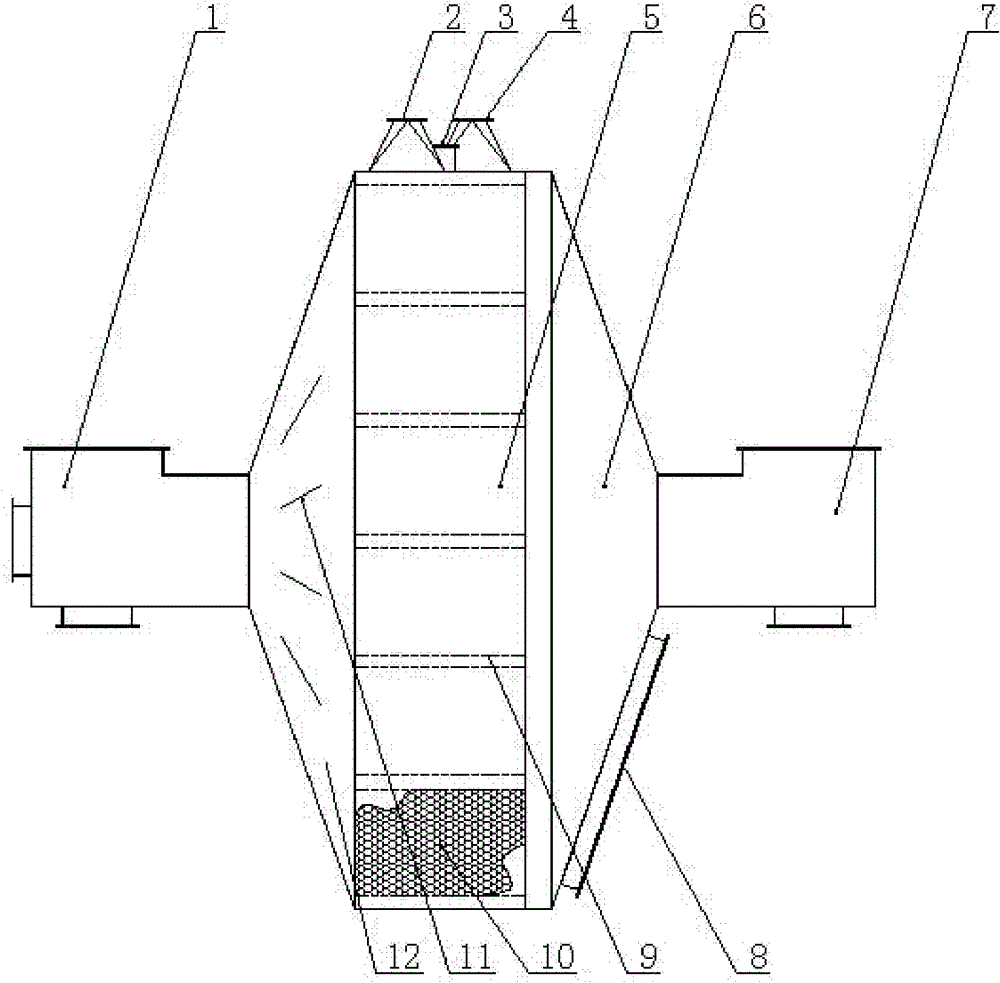
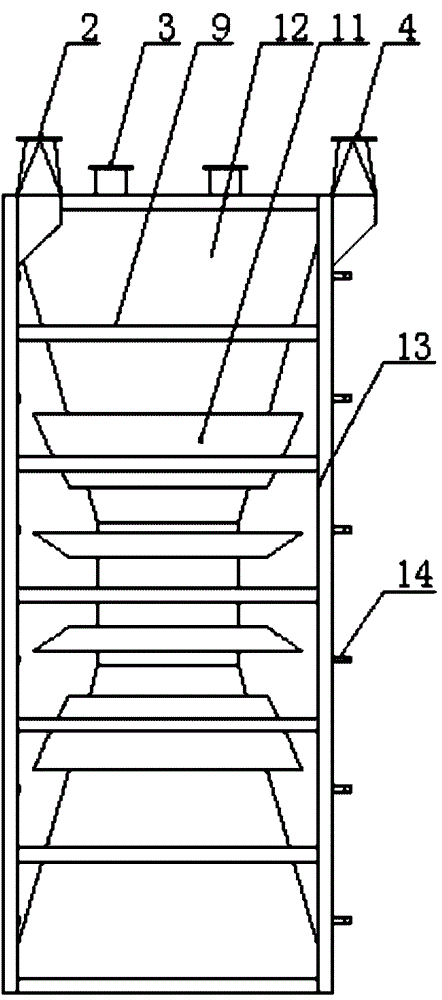
The invention relates to an energy-saving high-efficiency purification system for industrial volatilizable organic pollutant. A catalytic electric heater, a grid plate and a catalytic bed layer are arranged successively in the body of a catalytic combustion bed from top to bottom, wherein the first air outlet of the catalytic combustion bed is connected with the air inlet of a mixed-flow heat exchanger by a pipeline; an activated carbon plate of an adsorption bed, which is of a hollow structure, is communicated with a side wall of a hollow structure, and two side walls of a hollow structure are respectively provided with a hot air inlet and a hot air outlet; and the second air outlet of the catalytic combustion bed is connected with the hot air inlet of the side wall of a hollow structure of the adsorption bed by a heating fan of the adsorption bed. The system provided by the invention has a simple and reasonable structure, can effectively lower the energy consumption, improve the purification rate, prolong the service life of the catalyst, shorten the desorption flow time, improve the purification rate and reduce the operation cost, and is a safe and reliable energy-saving high-efficiency purification system for industrial volatilizable organic pollutants.

Description

technical field [0001] The invention belongs to the field of organic pollutant purification systems, in particular to an energy-saving efficient purification system for industrial volatile organic pollutants. Background technique [0002] The industrial volatile organic pollutant purification system currently mainly includes, including mixed flow heat exchanger, fresh air mixed flow fan, catalytic combustion bed, desorption electric heater, desorption circulation fan and adsorption bed, the first air outlet of catalytic combustion bed and new The air outlet of the air mixed flow fan is connected to the air inlet of the mixed flow heat exchanger through pipes, and the air outlet of the mixed flow heat exchanger is connected to the desorption circulating fan through the desorption electric heater and the adsorption bed. Although this system has a certain purification effect, it has the following problems: 1. Since the air heated up by the desorption electric heater needs to he...

Claims


Application Information

Patent Timeline
Patent Type & Authority Patents(China)
IPC IPC(8): B01D53/04B01D46/00F23G7/07
Inventor 朱殿兴刘光明刘宗瑜冯炘赵崇光李勤科耿兆玲熊树涛
Owner NANTONG ZHI HANG MECHANICAL & ELECTRICAL TECH CO LTD
Learn More