
Method for pulse-based ultra-broadband communication between at least one transmitting node and at least one receiving node

A technology of ultra-wideband communication and sending nodes, applied in transmission systems, electrical components, etc., can solve problems such as interference with data transmission, inability to communicate simultaneously, and data transmission conflicts

Inactive Publication Date: 2015-01-21
SIEMENS AG
View PDF2 Cites 0 Cited by
  • Summary
  • Abstract
  • Description
  • Claims
  • Application Information

AI Technical Summary

Problems solved by technology

From this arises the problem that in the case of multiple sending nodes and receiving nodes dividing the transmission medium, high bit rate UWB communication cannot be operated simultaneously with low bit rate UWB communication
Especially the high pulse energy of the low-bit-rate UWB transmission interferes with the high-bit-rate data transmission over a relatively wide range and leads to collisions of these two data transmissions in the commonly used frequency band

Method used


Image

  • Method for pulse-based ultra-broadband communication between at least one transmitting node and at least one receiving node
  • Method for pulse-based ultra-broadband communication between at least one transmitting node and at least one receiving node
  • Method for pulse-based ultra-broadband communication between at least one transmitting node and at least one receiving node

Examples


Embodiment Construction

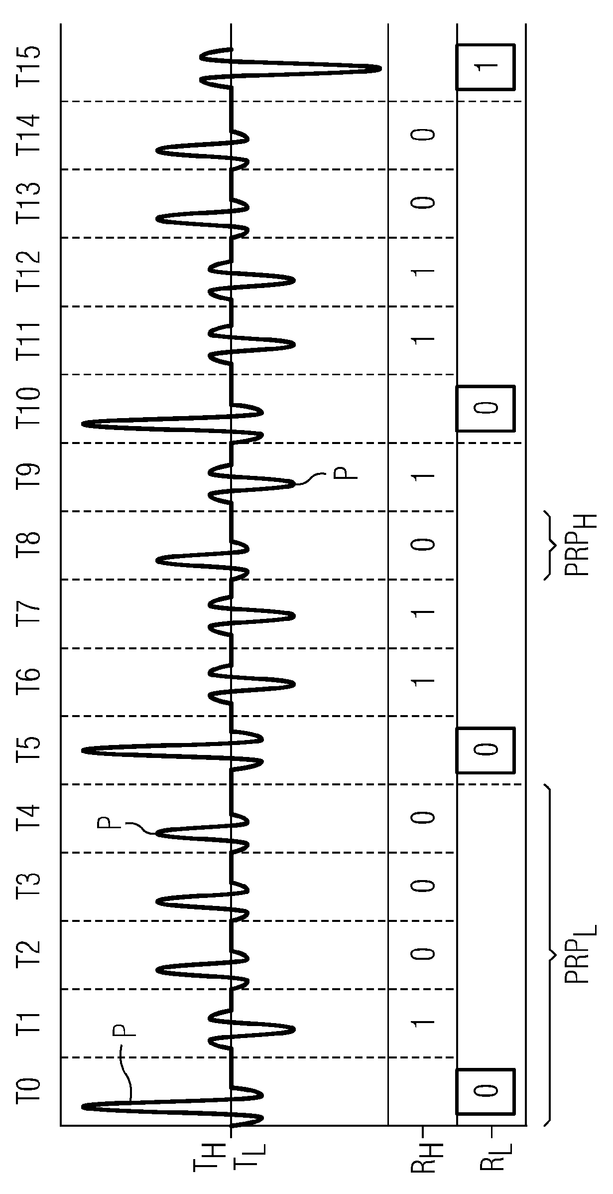
[0025] In the following, two embodiments of the method according to the invention will first be explained, in which the transmission of the UWB signal takes place consecutively by means of pulses in mutually consecutive time windows. In this case, a first data transmission with a low pulse rate and a high range and a second data transmission with a high pulse rate and a low range take place in the UWB signal based on these pulses.

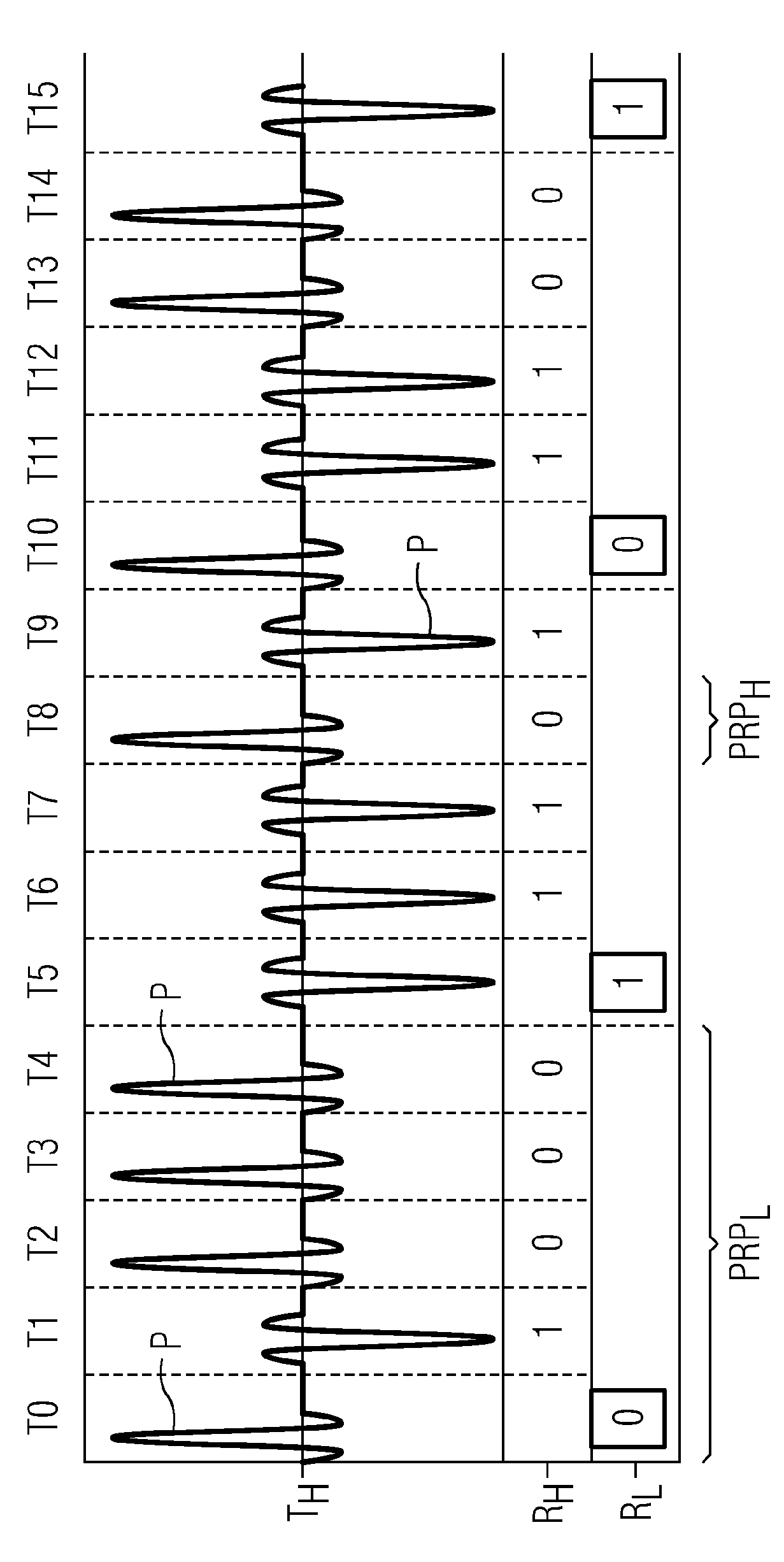
[0026] figure 1 A UWB signal according to a first embodiment of the method according to the invention is shown. exist figure 1 , the time axis extends in the horizontal direction, wherein the corresponding time windows in which a single pulse is transmitted in each case are denoted by T0, T1, . . . , T15. By way of example, some of these pulses are shown here with the reference symbol P. exist figure 1 scenario, through a so-called transceiver TH To generate UWB signals, the transceiver transmits at a high pulse rate. The transceiver is here a...


PUM


Abstract

An ultra-broadband signal having a plurality of pulses is transmitted from one or more transmitting nodes to one or more receiving nodes. In the ultra-broadband signal, data are transmitted by pulses having a first pulse rate in a first data transmission and by pulses having a second pulse rate in at least one second data transmission, with each second pulse rate higher than the first pulse rate. The pulses having the second pulse rate are transmitted in intervals, during which no pulses having the first pulse rate are transmitted. This has the advantage that by utilizing time gaps between pulses of the first data transmission, the data of a second data transmission can be transmitted at a higher pulse rate. The transmitting and receiving nodes need not be coordinated explicitly or coordinated from the outside.

Description

technical field [0001] The invention relates to a method for pulse-based ultra-wideband communication between at least one sending node and at least one receiving node. Background technique [0002] The present invention relates to the technical field of ultra-wideband communication, which is also referred to as UWB communication (UWB=Ultra Wide Band, ultra-wideband) below. UWB technology is a kind of proximity area radio communication that uses a very large frequency range with a bandwidth of at least 500MHz or at least 20% of the arithmetic mean of the lower limit frequency and the upper limit frequency of the frequency band used. In order to keep the interference between UWB communication and other wireless communication systems, such as WLAN, as low as possible, regulatory bodies have established for UWB signals an average maximum permissible energy when transmitting these signals. A variant of the UWB system is currently defined by the standard IEEE 802.15.4a. This st...

Claims


Application Information

Patent Timeline
Patent Type & Authority Patents(China)
IPC IPC(8): H04B1/7176H04B1/719H04B1/69
CPCH04B1/7176H04B1/719
Inventor J·洪德A·海因里希C·施温根施勒格尔
Owner SIEMENS AG
Learn More