
Lubrication device for hydraulic drawing machine

A lubricating device and wire drawing machine technology, which is applied in the direction of engine lubrication, lubricating pumps, distribution devices, etc., can solve the problems of guide rail slide wear, low working efficiency of wire drawing machine, equipment damage, etc.

Inactive Publication Date: 2011-09-14
刘立新
View PDF5 Cites 4 Cited by
  • Summary
  • Abstract
  • Description
  • Claims
  • Application Information

AI Technical Summary

Problems solved by technology

[0003] There are many kinds of hydraulic wire drawing machines used in known crushing roller or shelling roller wire drawing, and the use effects are different. Usually, more hydraulic wire drawing machines are used, mainly using two sets of flat belt deceleration drive wire drawing machines. Because large crushing rollers are very Heavy, the general size of the crushing roller with a size of Φ400×2100 weighs 1.8 tons, which is 3 times the usual weight. 1.6 tons, the total weight is about 3.4 tons, the working speed of the workbench is 7-11m / s, the workbench works back and forth, and when it reaches the end, the control valve reverses quickly, so that the workbench immediately moves in the opposite direction, forming a The large impact force and vibration force can only be operated at a reduced speed, generally down to about 5 meters, which makes the working efficiency of the wire drawing machine very low, and the requirements for the lubricating mechanism or device of this hydraulic wire drawing machine are relatively high. At present, the lubricating mechanism or device of the wire drawing machine adopts the roller refueling device in the oil tank, which needs to be refueled manually. If the refueling is not done in time, the guide rail slideway is often worn due to lack of oil, which will cause equipment damage and affect the service life of the equipment.

Method used


Image

  • Lubrication device for hydraulic drawing machine
  • Lubrication device for hydraulic drawing machine
  • Lubrication device for hydraulic drawing machine

Examples


Embodiment Construction

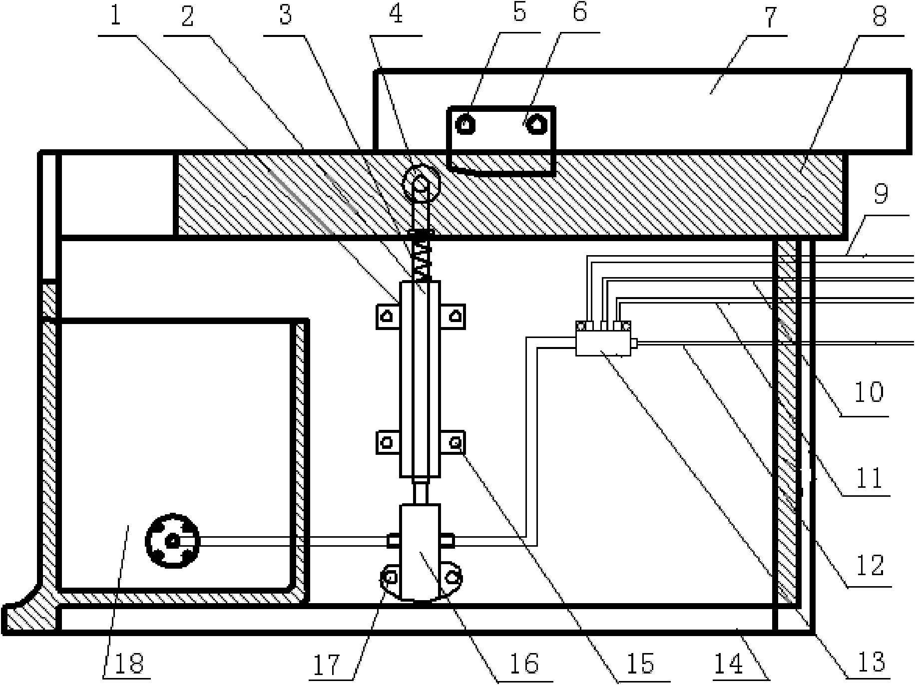
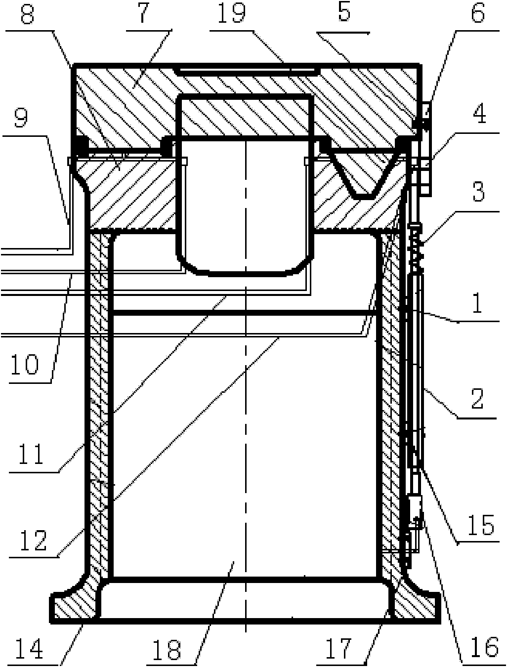
[0011] Specific embodiments of the present invention, such as figure 1 , 2 As shown, a lubricating device for a hydraulic wire drawing machine, a lubricating device for a hydraulic wire drawing machine, includes an oil tank 18 arranged under the wire drawing machine, an oil distributor 13 and various oil pipes, wherein each oil pipe includes a first oil pipe 9, The second oil pipe 10, the third oil pipe 11 and the fourth oil pipe 12 are characterized in that: there is a slide block 6 arranged on the sliding platform 7 of the wire drawing machine, and between the bottom of the slide block 6 and the oil tank 18 The roller plunger pump automatic oiling mechanism that cooperates with the slider 6, specifically the slider 6 of the lubricating device is fixed on the wire drawing machine sliding platform 7 by the slider fixing bolt 5, as figure 1 , 2 shown.

[0012] Said roller plunger pump automatic oil filling mechanism is made up of rolling pulley 4, guide rod 2, spring 3 on th...


PUM


Abstract

The invention relates to a lubrication device for a hydraulic drawing machine. The lubrication device comprises a fuel tank (18) arranged below the drawing machine, a path oil distributor (13) and path oil pipes. The lubrication device is characterized in that: the lubrication device is provided with a sliding block (6) arranged on a sliding platform of the drawing machine; an automatic oil injection mechanism for a roller plunger pump is matched with the sliding block (6) and is arranged between the lower side of the sliding block (6) and the fuel tank (18); the automatic oil injection mechanism consists of a rolling pulley (4), a guide rod (2), a spring (3) on the guide rod (2), a guide rod clamp iron track (1) and a fixing bolt (15), and a plunger fuel pump (16) and a fixing bolt (17), wherein the rolling pulley (4) is hinged with the guide rod (2); the rolling pulley (4) and the fixing bolt (15) are installed on the machine body (14) of the drawing machine through the guide rod clamp iron (1); the plunger rod of the plunger fuel pump (16) is connected with the lower end of the guide rod (2); and the pump body of the plunger fuel pump (16) is connected with the fuel tank (18) through a pipeline and then connected with the path oil distributor (13). The lubrication device has the characteristics of simple structure, low manufacturing cost, convenience of operation and maintenance, automatic and adequate oil supply, low abrasion and the like.

Description

[0001] 1. Fields: [0002] The invention relates to a hydraulic wire drawing machine lubrication technology for crushing or peeling rolls of oil material slabs in the oil industry, in particular to a hydraulic wire drawing machine lubricating device. 2. Background technology: [0003] There are many kinds of hydraulic wire drawing machines used in known crushing roller or shelling roller wire drawing, and the use effects are different. Usually, more hydraulic wire drawing machines are used, mainly using two sets of flat belt deceleration drive wire drawing machines. Because large crushing rollers are very Heavy, the general size of the crushing roller with a size of Φ400×2100 weighs 1.8 tons, which is 3 times the usual weight. 1.6 tons, the total weight is about 3.4 tons, the working speed of the workbench is 7-11m / s, the workbench works back and forth, and when it reaches the end, the control valve reverses quickly, so that the workbench immediately moves in the opposite dire...

Claims


Application Information

Patent Timeline
IPC IPC(8): F16N13/10F16N25/00
Inventor 刘立新刘立涛刘显树周丽娟
Owner 刘立新
Learn More