Eureka AIR delivers breakthrough ideas for toughest innovation challenges, trusted by R&D personnel around the world.

Rapid clamping mould box for battery pack welding

A kind of battery pole and fast technology, applied in battery pack parts, circuits, electrical components, etc., can solve the problems of unreliable self-locking performance, short clamping stroke, etc., to achieve the effect of long clamping stroke and reducing types

Inactive Publication Date: 2013-01-02
ZHAOQING LEOCH BATTERY TECH
View PDF0 Cites 0 Cited by
  • Summary
  • Abstract
  • Description
  • Claims
  • Application Information

AI Technical Summary

Problems solved by technology

Comb-tooth plates are used in conjunction with the mold box when welding the pole group, and the clamping mechanism of the current mold box mostly uses an eccentric wheel or a cam clamping mechanism. The clamping stroke of this kind of clamping mechanism is short, and the self-locking performance is not reliable.

Method used


Image

  • Rapid clamping mould box for battery pack welding
  • Rapid clamping mould box for battery pack welding
  • Rapid clamping mould box for battery pack welding

Examples


Embodiment Construction

[0022] The present invention will be further described in detail below through specific embodiments in conjunction with the accompanying drawings.

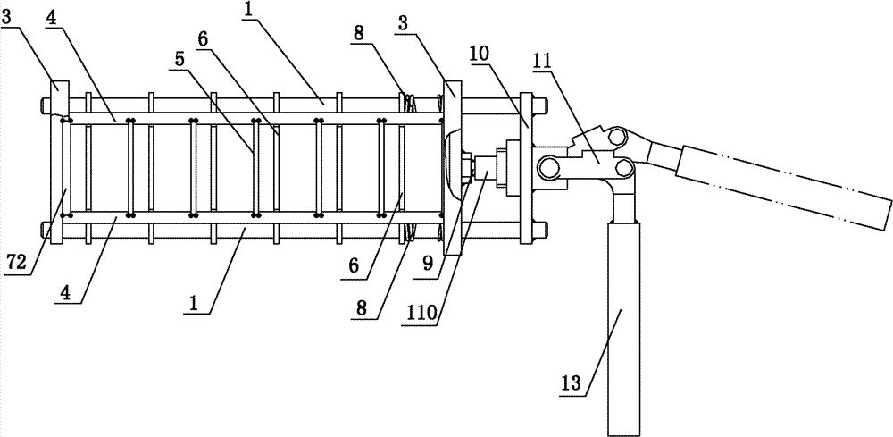
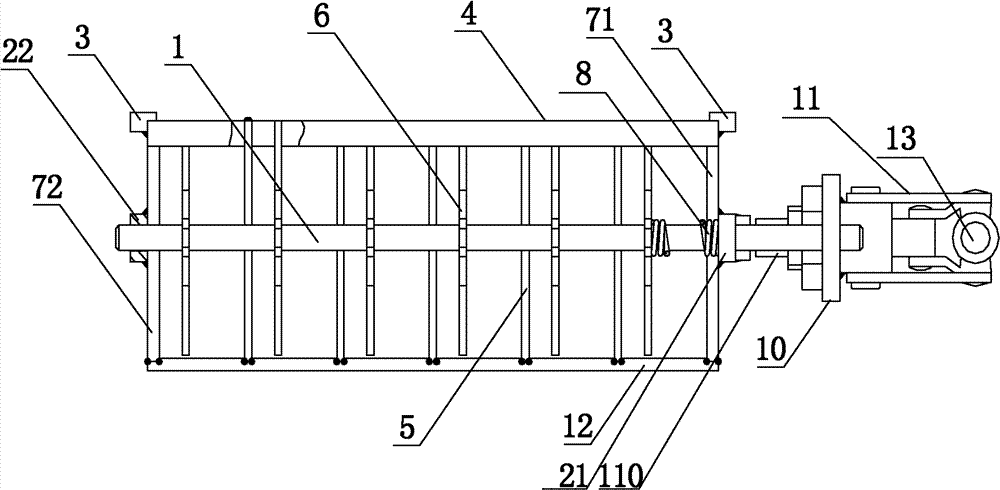
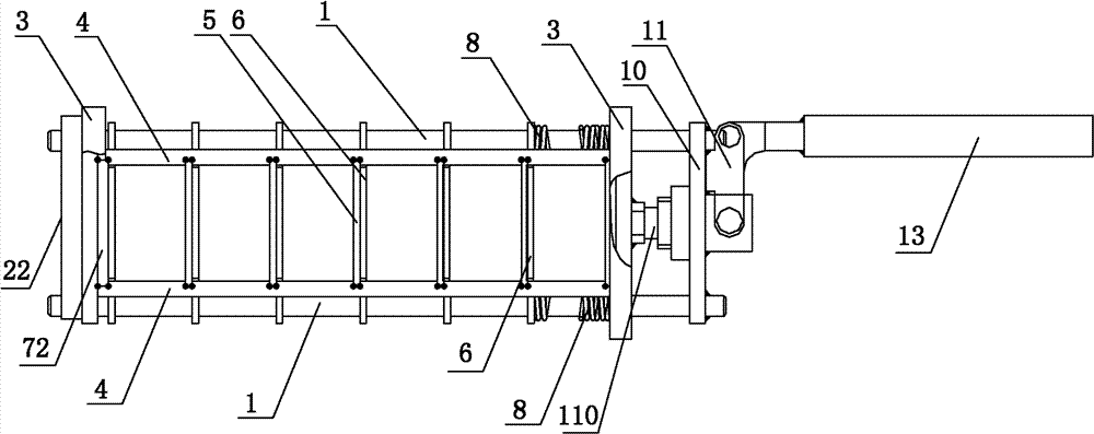
[0023] Please refer to figure 1 with figure 2 , The quick clamping mold box for battery pole group welding in this embodiment includes a movable mold box for containing the battery pole group, and a clamping mechanism for clamping the battery pole group contained in the movable mold box. Wherein, movable mold box is by base plate 12, is respectively fixed on the front end plate 71 and rear end plate 72 of this base plate 12 front and rear ends, and is arranged on this base plate 12 left and right sides, and is fixedly connected with front end plate 71 and rear end plate 72 Two side plates 4 are enclosed and formed, and a plurality of baffle plates 5 parallel to the front end plate 71 and the rear end plate 72 are fixed between the two side plates 4; wherein, the clamping mechanism includes a connecting plate 10, which is respect...


PUM


Abstract

The invention discloses a rapid clamping mould box which comprises a movable mould box and a clamping mechanism, wherein the movable mould box is defined by a baseplate, a front end plate, a rear end plate and two side plates, the front end plate and the rear end plate are respectively fixed at the front and rear ends of the baseplate, the two side plates are respectively arranged at the left andright sides of the baseplate and fixedly connected with the front end plate and the rear end plate, and a plurality of baffle plates parallel to the front end plate and the rear end plate are fixed between the two side plates; and the clamping mechanism is used for clamping battery packs, and comprises a connecting plate, two draw bars, a plurality of pressing plates and a rapid clamp, the pressing plates are fixed between the two draw bars and distributed at the intervals of the baffle plates, the rapid clamp is used for driving the connecting plate to make a forward and backward movement and fixedly connected with the connecting plate, the front ends of the two draw bars are respectively fixed at the two sides of the connecting plate, the rear ends of the two draw bars extend along the direction parallel to the side plates, and the connecting plate is fixedly connected with the rapid clamp. The rapid clamp drives the connecting plate to make a forward and backward movement along thedirection parallel to the draw bars, therefore, the clamping stroke of the clamping mould box is long, so that the clamping mould box is suitable to be used for battery packs with various thicknesses, and the type and quantity of the mould boxes are effectively reduced.

Description

technical field [0001] The invention relates to the technical field of storage batteries, in particular to a quick clamping mold box for welding battery pole groups. Background technique [0002] In the production process of lead-acid batteries, the welding of lead-acid battery electrode groups is a key process, that is, by connecting the positive and negative plates in parallel to achieve the doubling of the capacity of a single plate, and at the same time melting the lead electrodes to form a busbar . During the whole process, the plates, busbars, lead parts (poles, butt weldments, etc.) are connected as a whole, and the separators between the positive and negative plates constitute the core components of the lead-acid battery. [0003] At present, in order to ensure the performance of batteries assembled with glass fiber separators, it is required that the electrode assembly should have a certain assembly pressure when it is inserted into the battery container, that is, ...

Claims


Application Information

Patent Timeline
Patent Type & Authority Patents(China)
IPC IPC(8): H01M2/26
CPCY02E60/12Y02E60/10
Inventor 熊正林路俊斗孙守平
Owner ZHAOQING LEOCH BATTERY TECH
Why Eureka
Eureka Blog
Learn More