
Remote control controlled area network (CAN) bus testing device and method

A CAN bus and remote control technology, applied in the direction of electrical program control, comprehensive factory control, comprehensive factory control, etc., can solve problems such as difficult integration, inability to implement applications, inability to integrate the advantages of bus analyzers and bus oscilloscopes, etc., to achieve Save manpower and realize the effect of automation

Inactive Publication Date: 2013-08-14
NORTHWESTERN POLYTECHNICAL UNIV
View PDF0 Cites 0 Cited by
  • Summary
  • Abstract
  • Description
  • Claims
  • Application Information

AI Technical Summary

Problems solved by technology

But this method has some disadvantages: First, the common method is to use the CAN bus analyzer CANcaseXL and the CAN bus oscilloscope CANscope in isolation, making it difficult to integrate the advantages of the bus analyzer and bus oscilloscope into the system. In the test system, it is impossible to realize its application in the complex test system and complex network level; secondly, the computer connected to the bus analyzer CANcaseXL and the bus oscilloscope CANscope cannot run independently, and needs to be operated by someone, which will bring difficulties to the test work Once again, in the testing process, once limited by the factors of the site, the computer connected to the bus analyzer CANcaseXL and the bus oscilloscope CANscope is forced to be arranged separately from other computers in the test system, causing the computer connected to the bus analyzer and the bus oscilloscope to be separated. The measured CAN bus information cannot be reflected to other computers in the test system in a timely manner, which will cause difficulties for the entire test work

Method used


Image

  • Remote control controlled area network (CAN) bus testing device and method
  • Remote control controlled area network (CAN) bus testing device and method
  • Remote control controlled area network (CAN) bus testing device and method

Examples


Embodiment Construction

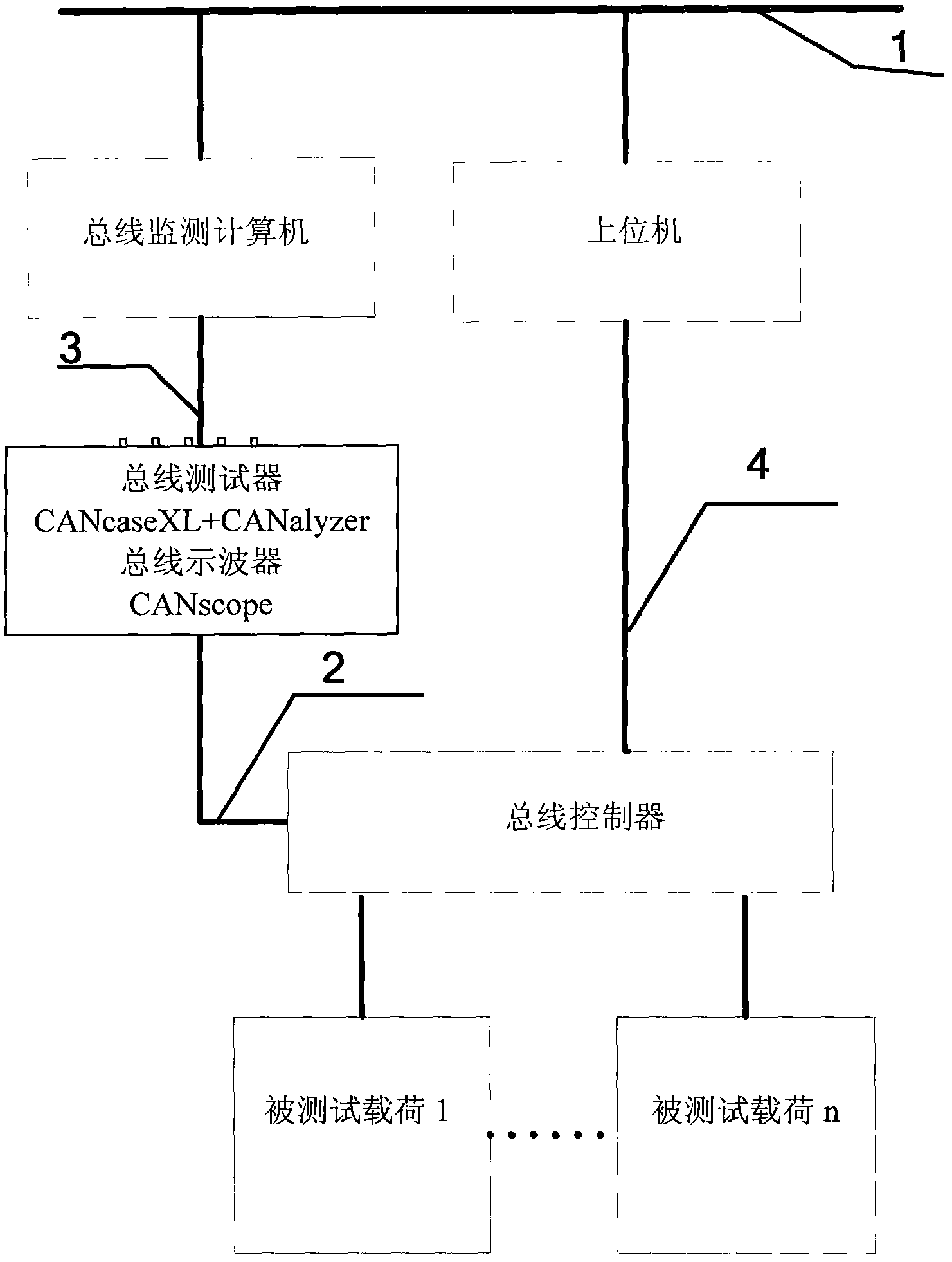
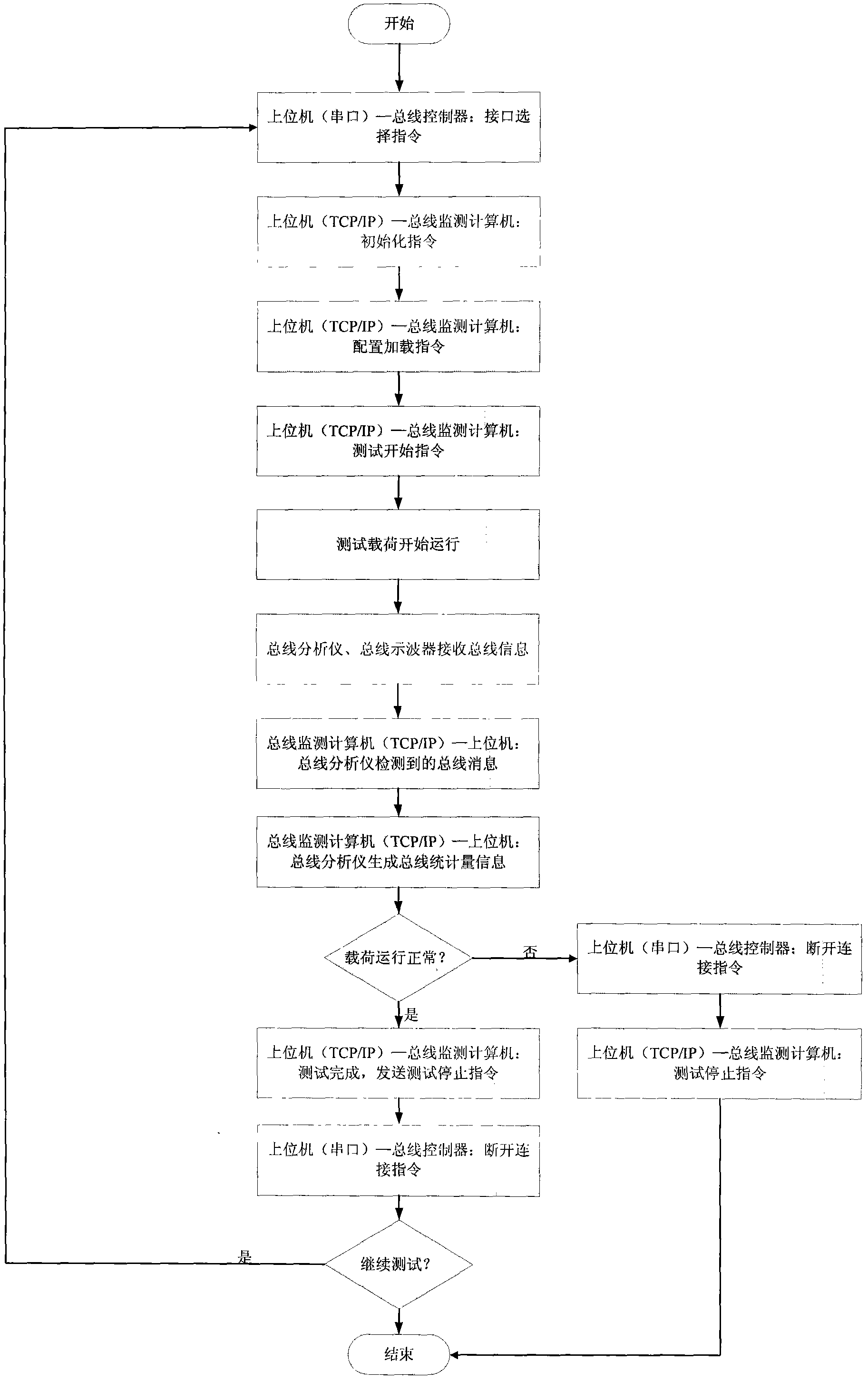
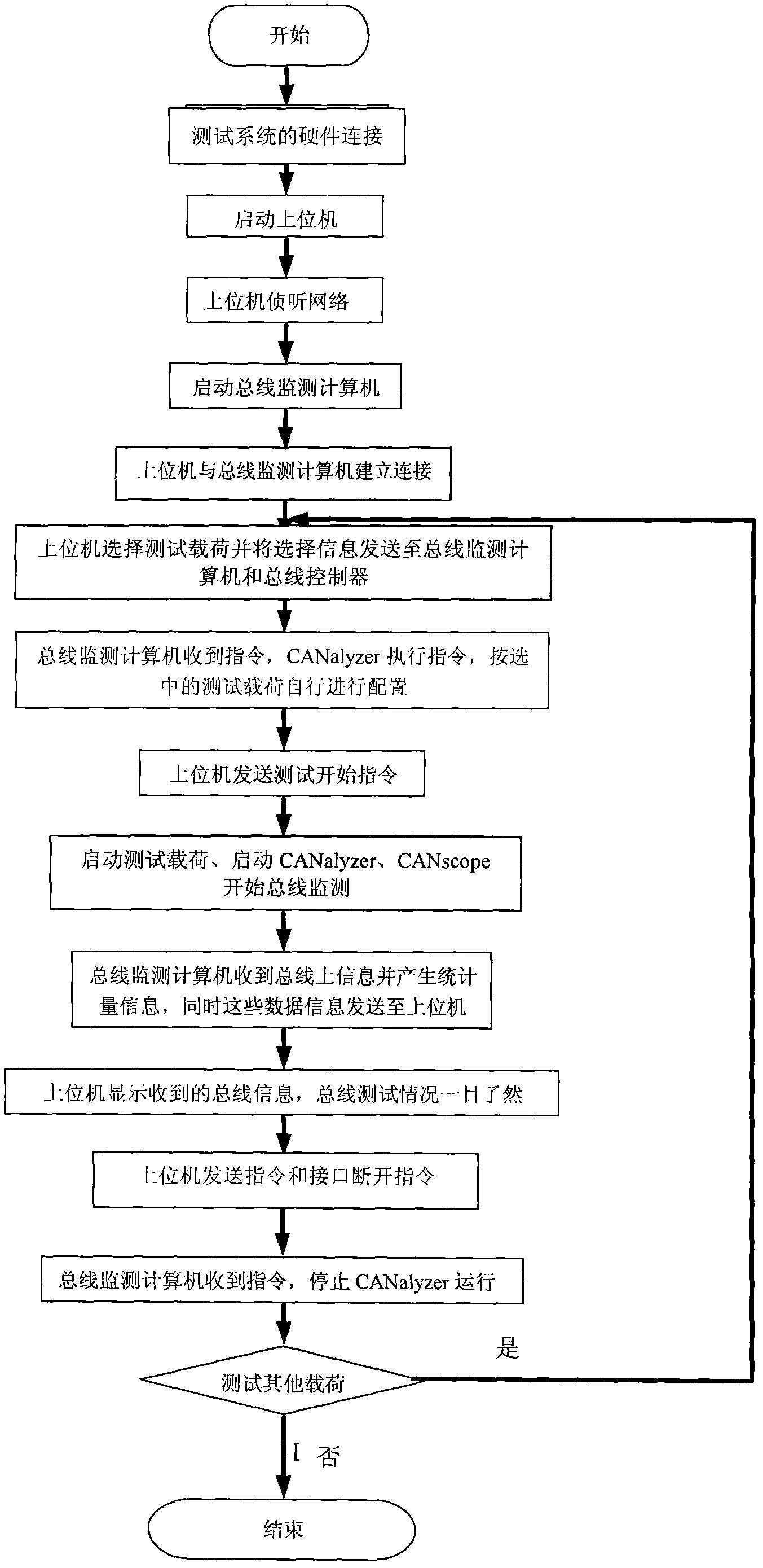
[0039] Device embodiment: refer to figure 1, The device of the present invention includes a host computer, a bus interface controller, a bus monitoring computer, a bus analyzer, a bus oscilloscope, tested loads 1 to n, a CAN bus and an Ethernet network. Connect the CAN bus analyzer and the CAN bus oscilloscope to a computer in the test system as a bus monitoring computer, and the bus monitoring computer is connected to the main control computer (host computer) in the test system through Ethernet. Use TCP / IP protocol for data transmission. Connect the CAN bus analyzer, CAN bus oscilloscope and the load to be tested to the CAN bus interface controller, thus forming a scalable CAN bus test network. It can be expanded according to the different requirements of the test system according to the load, so as to meet the test requirements. According to the test requirements, the host computer sends an interface selection command to the CAN bus interface controller, so that the CAN bu...


PUM


Abstract

The invention discloses a remote control controlled area network (CAN) bus testing device and method. The method comprises: a master control computer selects an instruction to a bus interface controller through a serial transmission interface and controls the connection and disconnection of a bus interface and a CAN bus of load to be tested; the master control computer transmits the instruction to a bus monitoring computer through a termination connection point / internet protocol (TCP / IP) protocol, and controls work of a bus analyzer and a bus oscilloscope; the bus analyzer and the bus oscilloscope receive data and instruction transmitted on the bus, and transmit the data and the instruction to the bus monitoring computer; and data required by the master control computer and statistic information related to the CAN bus can be transferred to the master control computer by the bus monitoring computer through the TCP / IP protocol. By utilizing the method, the labor force requirement is reduced, so that places and other factor limitations are overcome.

Description

technical field [0001] The invention relates to a CAN bus test device and a method thereof. Background technique [0002] At present, the commonly used CAN bus test method is to connect one end of the CAN bus analyzer CANcaseXL and the CAN bus oscilloscope CANscope to the computer, and the other end is directly connected to the CAN bus, and use the supporting software CANalyzer and CANscope to directly perform CAN bus information and Inspection of physical properties. In this way, the information on the CAN bus can be accurately analyzed, so as to complete the test of the bus load. But this method has some disadvantages: First, the common method is to use the CAN bus analyzer CANcaseXL and the CAN bus oscilloscope CANscope in isolation, making it difficult to integrate the advantages of the bus analyzer and bus oscilloscope into the system. In the test system, it is impossible to realize its application in the complex test system and complex network level; secondly, the co...

Claims


Application Information

Patent Timeline
Patent Type & Authority Patents(China)
IPC IPC(8): G05B19/418
CPCY02P90/02
Inventor 岳晓奎赵凯袁建平李彬
Owner NORTHWESTERN POLYTECHNICAL UNIV
Learn More