
Optical distance doubled dynamic collimation interferometer

An interferometer and dynamic technology, applied in the field of interferometers, can solve the problems of troublesome optical system cleaning environment, harsh lateral movement deviation in the vertical axis direction, and difficult to achieve high FTIR resolution, so as to achieve perfect cost and benefit, reduce volume and Weight, the effect of miniaturization

Active Publication Date: 2012-09-26
天津港东科技股份有限公司
View PDF3 Cites 0 Cited by
  • Summary
  • Abstract
  • Description
  • Claims
  • Application Information

AI Technical Summary

Problems solved by technology

It generally uses precision mechanical guide rails, corner mirrors or cat glasses as mirrors (moving mirror and fixed mirror). The lateral movement deviation in the vertical axis direction is more stringent, and the use of this mechanical guide generally requires the use of lubricating oil, which brings certain troubles to the clean environment of the optical system
Generally, the FTIR resolution of this structure is not easy to achieve high

Method used


Image

  • Optical distance doubled dynamic collimation interferometer
  • Optical distance doubled dynamic collimation interferometer
  • Optical distance doubled dynamic collimation interferometer

Examples


Embodiment Construction

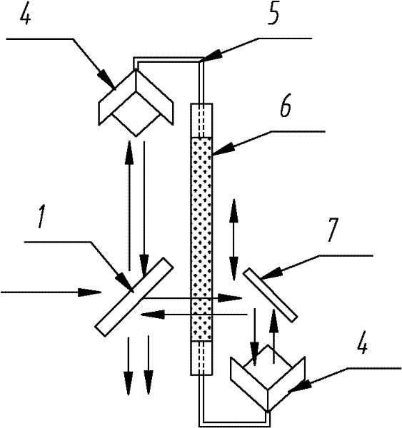
[0018] The structure of the double optical path dynamic collimation interferometer of the present invention is described in conjunction with the accompanying drawings.

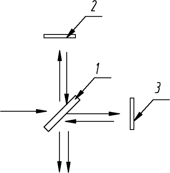
[0019] The double optical path dynamic collimation interferometer of the present invention is an improvement on the basis of the traditional classic Michelson interference optical path structure, and the optical path difference of the interferometer is twice the scanning distance of the moving mirror guide rail.

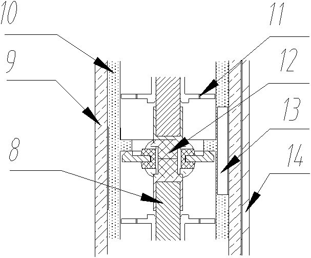
[0020] The multiple optical path dynamic collimation interferometer of the present invention, the interferometer includes a beam splitter, and the interferometer also includes two upper and lower corner mirrors 4, a connecting rod 5, a motion bearing 6, and a dynamic collimation mirror 7. A motion bearing 6 is provided on one side of the beam splitter 1, the beam splitter 1 and the motion bearing 6 are placed at an angle of 45 degrees, and the two ends of the motion bearing 6 are respectively connecte...


PUM


Abstract

The invention provides an optical distance doubled dynamic collimation interferometer. The optical distance doubled dynamic collimation interferometer comprises a beam splitter, a motion bearing is arranged at one side of the beam splitter, the beam splitter and the motion bearing are arranged in a manner of forming a 45-degree included angle, two ends of the motion bearing are respectively connected with a connecting rod, and two corner reflectors are respectively arranged on the connecting rods; a dynamic collimation reflector is arranged in a manner of forming the 45-degree included angle with the beam splitter, a transmission light of the dynamic collimation reflector is reflected to the corner reflector below, corresponding movable reflector is combined, and the corner reflector overthe movable reflector is used as a fixed reflector. The optical distance doubled dynamic collimation interferometer provided by the invention has the benefit that effective optical distance of the dynamic collimation interferometer is doubled without adding the scanning stroke of the movable reflector, and the resolution ratio of a FTIR is improved; structure of the interferometer is greatly simplified to be more compact, the volume and the weight of the interferometer can be greatly reduced, and implementation of miniaturization of the interferometer is facilitated; a dynamic collimation control system is used, the dynamic collimation reflector continuously adjust the posture according to the returned information, so that the interference can be always in the best status, and requirementon accuracy of guide rails is reduced. The optical distance doubled dynamic collimation interferometer implements the perfect match of the cost and the benefit.

Description

technical field [0001] The invention relates to an interferometer, which is a double optical path dynamic collimating interferometer applied to a Fourier transform infrared spectrometer (FTIR), and can also be used in a Fourier transform spectrometer. Background technique [0002] The interferometer is the core component of the Fourier transform infrared spectrometer. It is equivalent to the scanning mechanism of the traditional spectrometer. It controls the moving mirror to scan to obtain the full-band spectral interferogram. The infrared spectrum of the sample can be obtained by Fourier transforming the interferogram. [0003] In order to obtain an ideal spectrogram, a higher degree of modulation of the interferogram must be required. This has strict requirements on the lateral displacement and angular offset of the moving mirror during walking. The resolution of the Fourier transform infrared spectrometer is closely related to the travel of the moving mirror of the inter...

Claims


Application Information

Patent Timeline
Patent Type & Authority Patents(China)
IPC IPC(8): G01J3/45G01J3/02
Inventor 杜振贡王波
Owner 天津港东科技股份有限公司
Learn More