
Energy acquisition circuit of micro-power device driven by piezoelectricity-magnetoelectricity combined vibration

A vibration-driven, energy-harvesting technology, applied in the field of MEMS energy, to achieve the effect of improving output and storage efficiency and improving output and storage efficiency

Inactive Publication Date: 2011-08-31
ZHONGBEI UNIV
View PDF4 Cites 15 Cited by
  • Summary
  • Abstract
  • Description
  • Claims
  • Application Information

AI Technical Summary

Problems solved by technology

However, there are no relevant reports on the method and technology for energy harvesting of piezoelectric-magnetic-electric hybrid vibration-driven MEMS power generation devices.

Method used


Image

  • Energy acquisition circuit of micro-power device driven by piezoelectricity-magnetoelectricity combined vibration
  • Energy acquisition circuit of micro-power device driven by piezoelectricity-magnetoelectricity combined vibration
  • Energy acquisition circuit of micro-power device driven by piezoelectricity-magnetoelectricity combined vibration

Examples


Embodiment 2

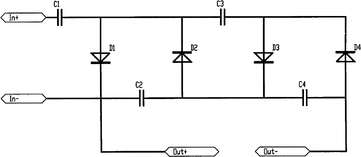
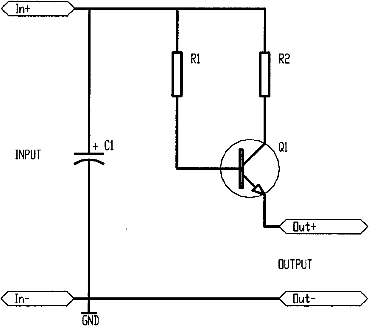
[0034] This embodiment passes Figure 4 The circuit shown realizes the present invention. This circuit integrates the circuits of the piezoelectric part and the magnetoelectric part, so that it has a systematic function, that is, the piezoelectric energy and the magnetoelectric energy are separately processed and finally integrated and stored. The piezoelectric output terminal is connected to "Input_1", the magnetoelectric output terminal is connected to "Input_2", and the two ends of "BAT+" and "BAT-" are respectively connected to the positive and negative poles of the supercapacitor.

[0035] The output current of this circuit, that is, the charging current I of the supercapacitor BAT =I PZT +I MAG , which is the result of the parallel connection of the output currents of the two parts. In this way, the output voltage is converted into current, which not only avoids the problem that the two energy output voltages cannot match, but also improves the charging efficiency of ...


PUM


Abstract

The invention discloses an energy gathering circuit of micro-power device driven by piezoelectricity-magnetoelectricity combined vibration. The device comprises a piezoelectricity output and a magnetoelectricity output, wherein the piezoelectricity output is connected with a piezoelectricity acquisition module and the magnetoelectricity output is connected with a magnetoelectricity module; the piezoelectricity module comprises a voltage multiplying rectifying circuit and a current charging circuit which are connected in sequence, a energy signal boosted by the voltage multiplying rectifying circuit can save energy in a super capacitor through the current charging circuit; and the magnetoelectricity acquisition module comprises a transformer, a bridge rectifier and a current charging circuit which are connected in sequence. The energy gathering circuit is used for energy acquisition of an MEMS (Micro-electro Mechanical Systems) generating set driven by piezoelectricity-magnetoelectricity combined vibration and can improve vibration energy output and storing efficiency, can effectively integrate piezoelectricity energy and magnetoelectricity energy, and can save energy which can support the MEMS device to work for a long time in the super capacitor.

Description

technical field [0001] The invention relates to an energy collection circuit of a piezoelectric-magnetoelectric composite vibration-driven micro-energy device, which belongs to the technical field of MEMS energy. Background technique [0002] Nowadays, MEMS products produced by micro-processing technology have been widely involved in many fields such as wireless sensor network, medical and health, biology, environmental monitoring, weather forecast, military, information and communication. With the development of MEMS technology, its products are increasingly required to be miniaturized, miniaturized, integrated, practical and automated. It is a very critical and urgent problem to be solved in MEMS technology. [0003] In recent years, micro high-energy batteries have developed vigorously, which can meet the energy supply needs of wireless components, but their energy density and energy supply life are still limited. In addition, for some distributed and embedded component...

Claims


Application Information

Patent Timeline
IPC IPC(8): H02N2/18H02J17/00H02J15/00H02J50/12
Inventor 丑修建郭涛熊继军张文栋关新锋张亚婷
Owner ZHONGBEI UNIV
Learn More