
Junction box of solar photovoltaic component

A solar photovoltaic and junction box technology, applied in the direction of photovoltaic modules, photovoltaic power generation, contact parts, etc., can solve the problems of weak current bearing capacity, easy to break, loose nuts, etc., to reduce contact resistance, prolong service life, and shorten length Effect

Inactive Publication Date: 2011-08-31
苏州恒宏模塑科技有限公司
View PDF14 Cites 12 Cited by
  • Summary
  • Abstract
  • Description
  • Claims
  • Application Information

AI Technical Summary

Problems solved by technology

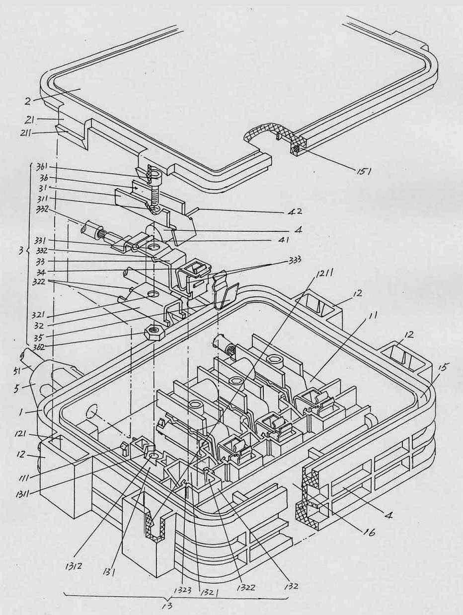
[0006] In short, the above-mentioned patents and patent application schemes have positive significance for the heat dissipation of the junction box, but there are still the following shortcomings: one is that the extension is formed on the box cover The inlays are easily damaged, because the above-mentioned prior art often uses the inlays and the bottom of the inlays formed on the junction box body to be fitted or hooked, that is to say, the inlays are matched with the bottom of the insets , so when the bypass diode in the junction box body needs to be replaced, it is easy to break due to the lengthy inlays; the second is that the fixing method of the conductive connection mechanism in the junction box body is unreasonable, and the nuts are usually pre-armored On the bottom wall of the junction box body, it is integrated with the junction box body, or screw holes are provided on the bottom wall of the junction box body (lines 3 to 9 of paragraph 0024 on page 3 of the instruction manual of CN101944546A), After the fixing screw passes through the hole on the conductive connection plate, the fixing screw is screwed into the nut armored on the bottom wall of the junction box or screwed into the screw hole on the bottom wall, so that the conductive connection mechanism fixed in the junction box
However, when heated (heat generated by the bypass diode), the nut pressed together with the bottom wall of the junction box will loosen, which will lose its effect on the positioning of the bypass diode, affect the electrical connection effect, and even cause an open circuit; The third is that the structure of the conductive connection mechanism is unreasonable, so that the contact resistance of the bypass diode is large, the temperature rise is large when the bypass diode flows through the current, and the current bearing capacity is weak, which affects the service life of the bypass diode

Method used


Image

  • Junction box of solar photovoltaic component
  • Junction box of solar photovoltaic component

Examples


Embodiment Construction

[0023] In order to enable the examiners of the patent office, especially the public, to understand the technical essence and beneficial effects of the present invention more clearly, the applicant will describe in detail the following in the form of examples, but none of the descriptions to the examples is an explanation of the solutions of the present invention. Any equivalent transformation made according to the concept of the present invention which is merely formal but not substantive shall be regarded as the scope of the technical solution of the present invention.

[0024] Please see figure 1 , a junction box body 1 with a substantially rectangular parallelepiped (or cube) shape is given, the junction box body 1 is molded from non-metallic materials, and plastic molding is used in this embodiment. When molding the junction box body 1, the box cavity 11, the lower pressure plate positioning flange 111, the foot seat 12, the conductive connection mechanism seat 13, the hea...


PUM


Abstract

The invention discloses a junction box of a solar photovoltaic component and belongs to the technical field of solar battery components. The junction box comprises a junction box body, a box cover, a group of bypass diodes and a group of conductive connection mechanisms, wherein the junction box body is provided with a box cavity and an embedding pin seat; the box cover is provided with an embedding pin; the group of bypass diodes are provided with first pins and second pins and arranged in the box cavity; the group of conductive connection mechanisms are arranged in the box cavity; and at least one bypass diode is arranged between each two adjacent conductive connection mechanisms. The junction box is characterized in that: a conductive connection mechanism seat is formed in the box cavity; the conductive connection mechanism seat comprises a lower pressing plate seat and a conductive connecting plate fitting seat; and the conductive connection mechanisms comprise upper and lower pressing plates, a conductive connecting plate, a first wire clamp and a second wire clamp. The junction box has the advantages of reducing contact resistance and temperature rise, prolonging the service life of each bypass diode, always guaranteeing the clamping effects on the first and second pins of the bypass diodes without influence of deformation of the heated junction box body, shortening the length of the embedding pin, and contributing to enhancement of the rigidity of the embedding pin to avoid breakage.

Description

technical field [0001] The invention belongs to the technical field of solar cell components, and in particular relates to a solar photovoltaic component junction box. Background technique [0002] The solar photovoltaic junction box is an important part of outputting solar power. It is a transitional device that connects the solar cell leads with the external leads. It usually consists of a box cover, a junction box body, a bypass diode installed in the junction box body, wires and cables and The conductive connection mechanism is formed. The function of the aforementioned bypass diode is to avoid damage to the solar photovoltaic cell due to reverse charging and to prevent the normal operation of the entire solar photovoltaic cell assembly from being compromised due to a short circuit of one solar photovoltaic cell. [0003] As is well known in the industry, when solar photovoltaic power generation, the current will flow through the aforementioned bypass diodes in the body...

Claims


Application Information

Patent Timeline
Patent Type & Authority Applications(China)
IPC IPC(8): H01L31/048H01R13/02H01R4/28H02S40/34
CPCY02E10/50
Inventor 胡正平
Owner 苏州恒宏模塑科技有限公司
Learn More