Current measurement device
A current measurement device and current technology, applied in measurement devices, measurement of electrical variables, voltage/current isolation, etc., can solve problems such as inability to support super-large current measurement, measurement accuracy, poor temperature characteristics, and low linear measurement range, etc. Achieve the effect of wide linear measurement range, good temperature characteristics and low power consumption
- Summary
- Abstract
- Description
- Claims
- Application Information
AI Technical Summary
Problems solved by technology
Method used
Image
Examples
Embodiment 1
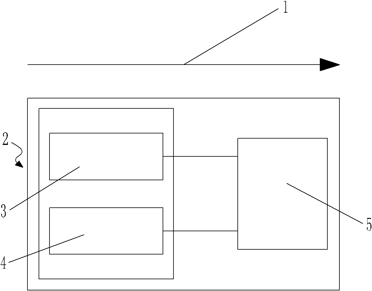
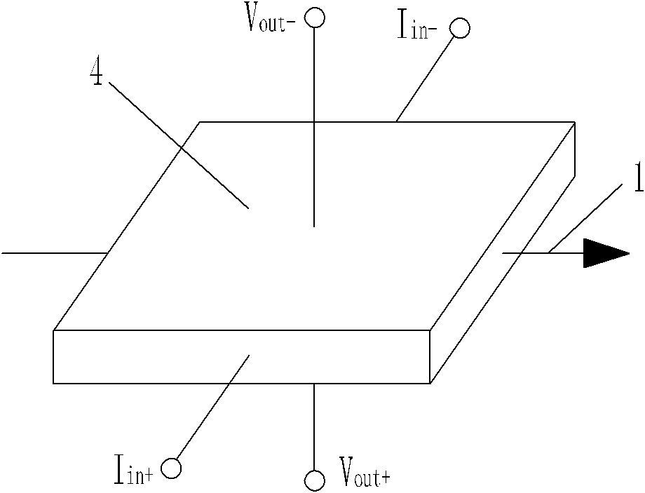
[0021] Embodiment one: as attached figure 1 As shown, the current measuring device includes a measuring unit 2, and the measuring unit 2 includes a first sensor 3 arranged parallel to the tangential direction of the magnetic field generated around the conducting wire and a second sensor arranged parallel to the first sensor 3 4. The first sensor 3 is a TMR sensor, and the second sensor 4 is a Hall sensor. The dedicated ASIC chip 5 is packaged together, and the electromagnetic principle of the Hall sensor is as attached figure 2 As shown, where Iin+ and Iin- are the current input terminals, which are input from opposite ends of the diaphragm, and Vout+ and Vout- are the output voltage terminals, which are respectively drawn out from the direction perpendicular to the surface of the diaphragm, so that the magnetic field around the current-carrying wire The direction of 1 is perpendicular to the direction of the input circuit and the output voltage. According to the working cha...
Embodiment 2
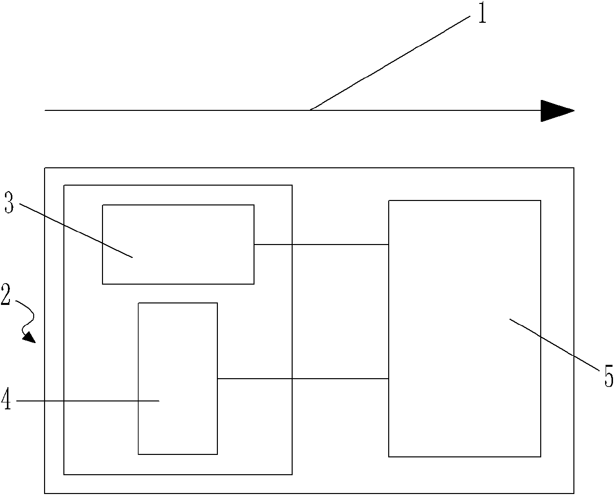
[0022] Embodiment two: as attached image 3 As shown, the current measuring device includes a measuring unit 2, and the measuring unit 2 includes a first sensor 3 parallel to the tangential direction of the magnetic field 1 around the conducting wire and a second sensor perpendicular to the first sensor 3. 4. The first sensor 3 is a TMR sensor, and the second sensor 4 is a Hall sensor, both of which are respectively connected to a sensor-specific ASIC chip 5 that matches both, and the first sensor 3 and the second sensor 4 and the sensor-specific ASIC chip 5 are packaged together, and the electromagnetic principle of the Hall sensor is as attached Figure 4 As shown, where Iin+ and Iin- are the current input terminals, which are input from the opposite ends of the diaphragm, Vout+ and Vout- are the output voltage terminals, and are respectively drawn from the other pair of opposite ends of the diaphragm, so that the current-carrying wire The direction of the surrounding magne...
Embodiment 3
[0023] Embodiment three: as attached Figure 5 As shown, the current measuring device includes a measuring unit 2, and the measuring unit 2 includes a first sensor 3 parallel to the tangential direction of the magnetic field 1 around the conducting wire and a second sensor 3 arranged at an angle θ with the first sensor 3. Sensor 4, wherein, 0° Figure 6 As shown, define the component of the magnetic field 1 around the current-carrying wire in the direction perpendicular to the second sensor 4 as H', then the H' measured by the second sensor 4=H×cos(π-θ), so H' is less than H, so use the TMR sensor with a lower range to measure a component of the magnetic field 1 around the current-carrying wire, and then calculate the size of the magnetic field 1 around the current-carrying wire through related formulas, so as to realize the measurement of the current in the current-carrying wire In this embodiment, the Hall sensor with a higher range is not needed, and the sensitivity of the T...
PUM
 Abstract
Description
Claims
Application Information
 - R&D Engineer
- R&D Manager
- IP Professional
- Industry Leading Data Capabilities
- Powerful AI technology
- Patent DNA Extraction
Browse by: Latest US Patents, China's latest patents, Technical Efficacy Thesaurus, Application Domain, Technology Topic, Popular Technical Reports.
© 2024 PatSnap. All rights reserved.Legal|Privacy policy|Modern Slavery Act Transparency Statement|Sitemap|About US| Contact US: help@patsnap.com


