
A method for determining a plume field thermal effect and a dynamic effect of a 10N thruster

A determination method and thruster technology, applied in aerodynamic tests, instruments, and testing of machine/structural components, etc., can solve problems such as unrealistic, large amount of calculation, and increased demand for computer power, so as to improve engineering applicability. range, improved computing speed and efficiency, and the effect of improved efficiency

Active Publication Date: 2013-03-13
CHINA ACADEMY OF SPACE TECHNOLOGY
View PDF4 Cites 0 Cited by
  • Summary
  • Abstract
  • Description
  • Claims
  • Application Information

AI Technical Summary

Problems solved by technology

A fatal shortcoming of the DSMC method is that the demand for computer power increases due to a large number of calculations.
At present, computer parallel computing is usually used to overcome the problem of large amount of calculation in DSMC method, but for satellite engineering applications, this is not realistic, especially it cannot give efficient and clear analysis conclusions in the early design stage of satellites

Method used


Image

  • A method for determining a plume field thermal effect and a dynamic effect of a 10N thruster
  • A method for determining a plume field thermal effect and a dynamic effect of a 10N thruster
  • A method for determining a plume field thermal effect and a dynamic effect of a 10N thruster

Examples


Embodiment Construction

[0033] The implementation process of the present invention will be described in detail below in conjunction with the accompanying drawings and embodiments.

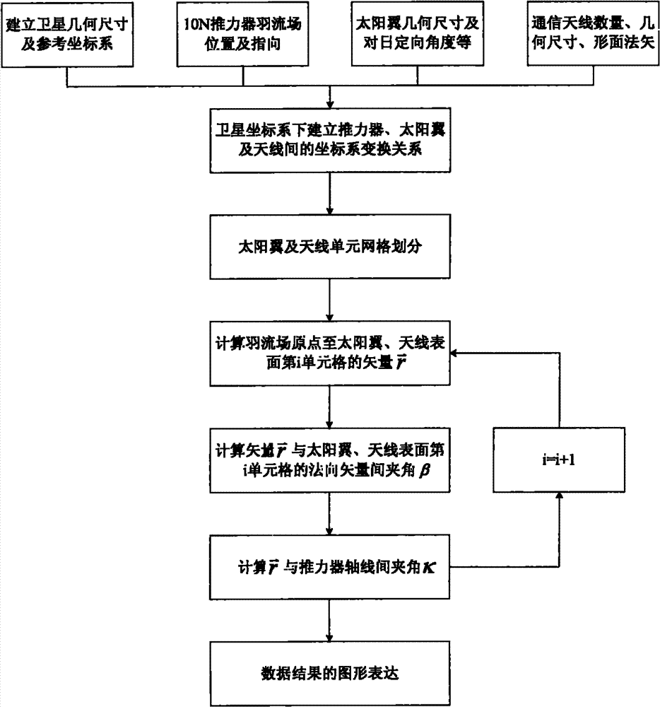
[0034] The present invention describes the distribution of the plume field, and its ultimate purpose is to analyze the influence of the plume field on the thermal effect and the dynamic effect of sensitive devices such as solar wings and communication antennas on the satellite surface. Such as figure 1 Shown, the concrete steps of the present invention are as follows:

[0035] (1) First establish the satellite geometric dimensions and satellite coordinate system; at the same time, establish the position and direction of the plume field in the 10N thruster body coordinate system, its geometric size and sun orientation angle in the solar wing body coordinate system, and the communication antenna body coordinates Link its geometric dimensions and surface normal vector parameters;

[0036] For communication satellites, the ...


PUM


Abstract

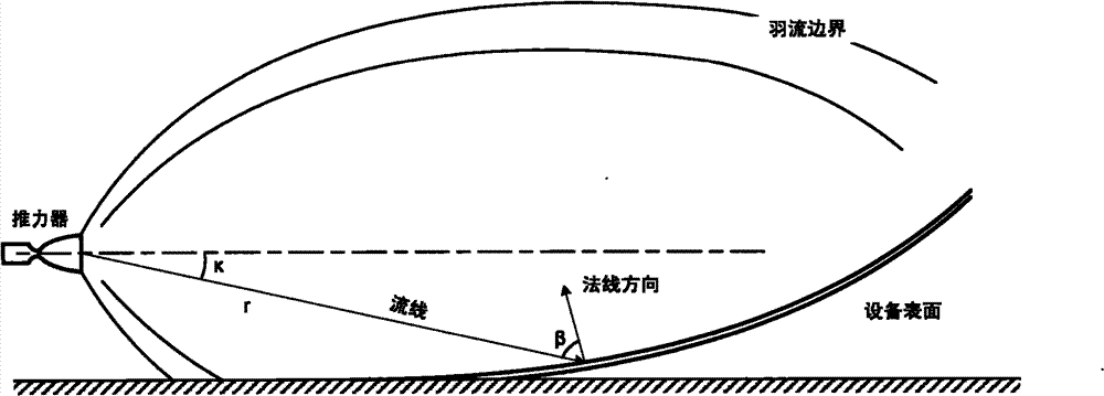
The invention provides a method for determining a plume field thermal effect and a dynamic effect of a 10N thruster. The method includes the steps of (1) establishing satellite geometric dimensioning and a satellite coordinate system, a location and a direction of the plume field under a 10N thruster coordinate system, geometric dimensioning and a directional angle towards the sun of the plume field under a sun wing coordinate system, and geometric dimensioning and shape-surface normal vector parameters under a communicational antenna coordinate system; (2) transforming the parameters of the thruster, the sun wing and the communicational antenna referred in step (1) into the satellite coordinate system; (3) dividing the sun wing and the communicational antenna into grid units, and calculating vectors of the plume field original points of all the grids to the ith grid unit of the sun wing and the surface of the communicational antenna, an included angle beta between the vector and the normal vector of the ith grid unit of the sun wing and the surface of the communicational antenna, and an included angle kappa between the vector and a thruster axis; (4) calculating the disturbing force and heat flow distribution of the plume field of the thruster according to the vector of each grid unit, beta and kappa calculated previously.

Description

technical field [0001] The invention relates to satellite general layout design and optimization thereof, and can be used as a reference for satellite thermal design and satellite control design at the same time. Background technique [0002] The plume refers to the airflow ejected by the satellite engine when it is working under high vacuum. It is shaped like a feather at the nozzle, so it is called the plume. The composition of the plume is complex, including molecular pollutants and particle pollutants, such as incompletely burned fuel droplets, combustion chamber wall particles, etc. In the space environment, the ejected gas will expand rapidly, become thinner and thinner, and can extend a long distance to form a plume, and a part of the gas will form a backflow and hit the surface of the spacecraft itself, directly affecting the spacecraft The working performance and life of the coating, especially the harmful effect on the thermal control coating and the surface of th...

Claims


Application Information

Patent Timeline
Patent Type & Authority Patents(China)
IPC IPC(8): G01M9/00
Inventor 李洋夏永泉吕红剑李学林王敏魏强
Owner CHINA ACADEMY OF SPACE TECHNOLOGY
Learn More