
Magnesium smelting reduction deslagging and residual heat recycling device and process

A waste heat recovery device and magnesium smelting technology, applied in the field of metal magnesium smelting, can solve the problems of environmental pollution, dust environmental pollution, and can only be used for underground burial.

Inactive Publication Date: 2011-08-31
宁夏惠冶镁业集团有限公司
View PDF2 Cites 14 Cited by
  • Summary
  • Abstract
  • Description
  • Claims
  • Application Information

AI Technical Summary

Problems solved by technology

[0002] At present, in the existing magnesium smelting industry, the waste slag in the smelting furnace after magnesium smelting is mostly cleaned by manual slag removal, that is, the slag is manually removed from the reduction tank in the reduction furnace. Dust is generated when the slag falls directly to the ground; in the dusty environment, the slag is manually loaded into the trolley, and secondary dust is generated while the slag is loaded into the trolley. Three times of dust; in the process of slag extraction, slag transportation, and slag unloading, the human body directly faces the slag with furnace temperature and the generated dust, secondary dust, and tertiary dust, which makes the working environment of people very bad, and at the same time, it is harmful to human health. It is very harmful, and this process causes the heat of the magnesium slag to be lost in vain in the slag field, and the unloaded magnesium slag can only be used for underground burial; at the same time, the dust generated during the slag discharge process causes serious pollution to the environment, and the ground burying The slag can only be treated as waste, which will pollute the environment again

Method used


Image

  • Magnesium smelting reduction deslagging and residual heat recycling device and process
  • Magnesium smelting reduction deslagging and residual heat recycling device and process
  • Magnesium smelting reduction deslagging and residual heat recycling device and process

Examples


Embodiment Construction

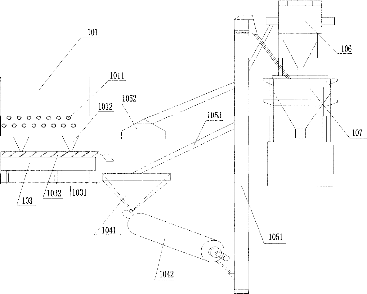
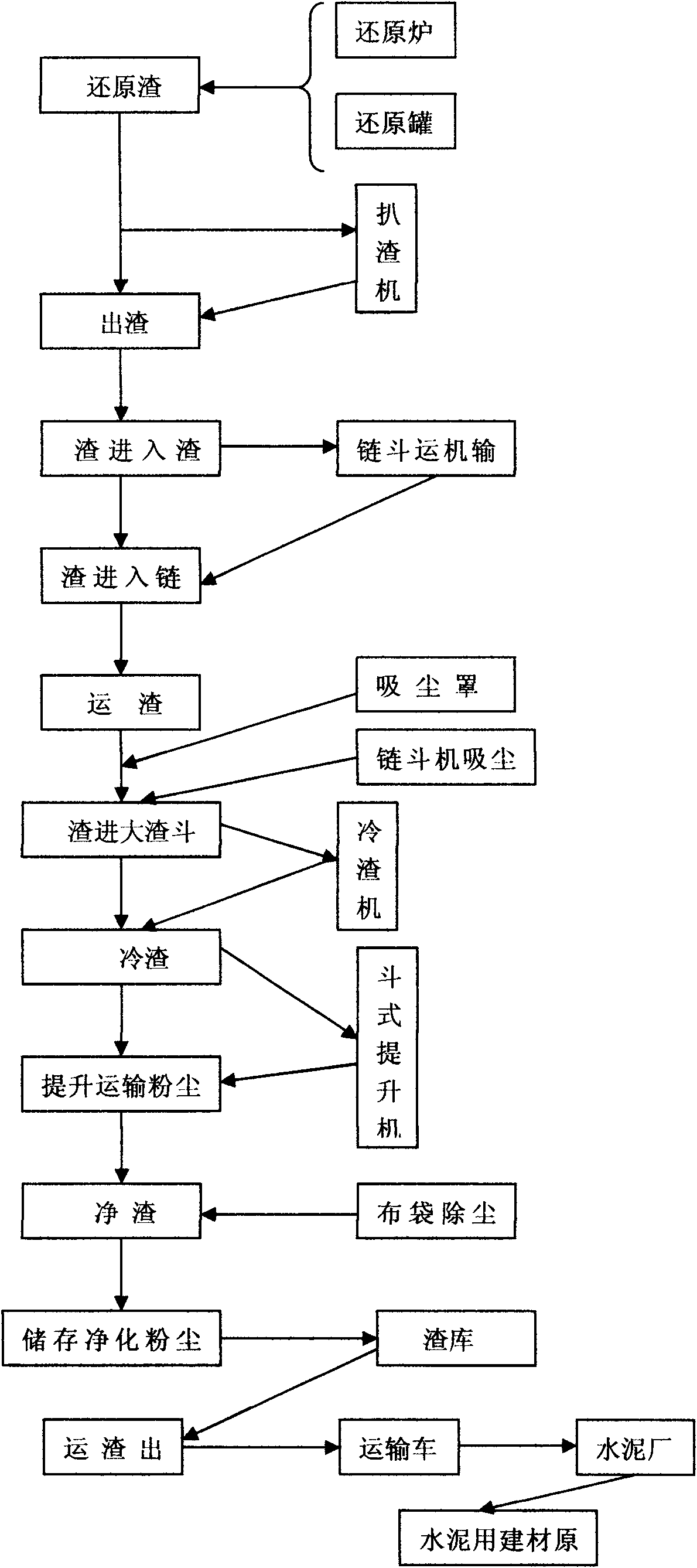
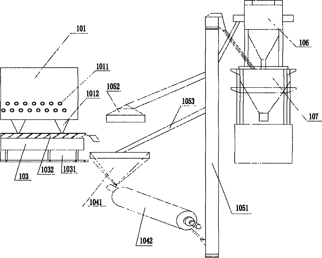
[0024] It is composed of reduction furnace 101, slag removal machine 102, chain bucket conveyor 103, slag cooler 104, bucket elevator 105, bag filter 106 and slag storage 107; reduction furnace 101 is composed of reduction tank 1011 and slag hopper 1012, The reduction tank 1011 is installed in the reduction furnace 101 to carry out the magnesium slag reduction reaction; the slag receiving hopper 1012 under the reduction furnace 101 is used to accept the slag from the reduction reaction; the slag removal machine 102 is installed in front of the reduction furnace 101, The slag scraper 102 has a spiral scraper, which is used to scrape out the slag in the reduction tank 1011; the front of the reduction furnace 101 is equipped with a continuously running chain bucket conveyor 103, and multiple chain bucket conveyors 103 are installed on the chain bucket conveyor 103. Chain hopper 1031, chain hopper 1031 is used to store the slag discharged from slag hopper 1011; slag cooler 104 is c...


PUM


Abstract

The invention relates to a magnesium smelting reduction deslagging and residual heat recycling device and process, belonging to the field of metal magnesium smelting, in particular to a magnesium smelting reduction automatic deslagging and residual heat recycling device and technology. The device comprises a reducing furnace, a deslagging machine, a chain bucket conveyor, a slag cooling machine, a bucket elevator, a bag-type dust collector and a slag storeroom; mechanical automation is realized in whole deslagging, transportation, cooling, conveying and storage processes; the waste slag temperature is reduced from 1,000 DEG C or so to below 100 DEG C by the slag cooling machine; the residual heat of the waste slag is effectively recycled, and energy saving and emission reduction are realized; the waste slag does not fall on the ground in the deslagging process and is dry powdery slag after cooled and can be used as a building cement raw material, and the aim of changing waste materialinto things of value is achieved; and operation and storage are basically sealed in the whole process without environmental pollution.

Description

Technical field: [0001] The magnesium smelting reduction slag discharge and waste heat recovery device and process of the present invention belong to the field of metal magnesium smelting, and in particular relate to the magnesium smelting reduction slag automatic slag discharge device and waste heat recovery technology. Background technique: [0002] At present, in the existing magnesium smelting industry, the waste slag in the smelting furnace after magnesium smelting is mostly cleaned by manual slag removal, that is, the slag is manually removed from the reduction tank in the reduction furnace. Dust is generated when the slag falls directly to the ground; in the dusty environment, the slag is manually loaded into the trolley, and secondary dust is generated while the slag is loaded into the trolley. Three times of dust; in the process of slag extraction, slag transportation, and slag unloading, the human body directly faces the slag with furnace temperature and the genera...

Claims


Application Information

Patent Timeline
Patent Type & Authority Applications(China)
IPC IPC(8): C22B26/22
CPCY02P10/20
Inventor 吴振荣田学忠魏建军李永泽李秀玲田军
Owner 宁夏惠冶镁业集团有限公司
Learn More